
Page 584 - Divyank Tyagi
P. 584
550 | ChapTeR 13 Modeling Floors, Ceilings, and rooFs
11. Switch to the Modify | Sweep tab in the ribbon and click the Finish Edit Mode icon from
the Mode panel.
12. Switch to the Modify | Void Sweep tab in the ribbon and select Cut ➢ Cut Geometry in
the Geometry panel. Pick the void sweep and then the floor at Level 1.
13. Click Finish Model in the In-Place Editor panel at the right end of the ribbon.
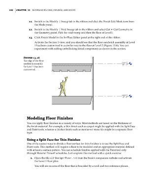
Activate the Section 1 view, and you should see that the floor sandwich assembly at Level
1 has been customized in a similar way to the floor at Level 2 (Figure 13.16). You can
experiment with adding embellishing detail components as shown in the section.
Figure 13.16
The edge of the floor
sandwich assembly
for level 1 has been
customized.
Modeling Floor Finishes
You can apply floor finishes in a variety of ways. Most methods are based on the thickness of
the finish material. For example, a thin finish such as carpet might be applied with the Split Face
and Paint tools, whereas a thicker finish such as mortar-set stone tile might be a separate floor
type.
Using a Split Face for Thin Finishes
One of the easiest ways to divide a floor surface for thin finishes is to use the Split Face and
Paint tools. This method will require a floor to be modeled and an appropriate material defined
with at least a surface pattern. You can schedule finishes applied with the Paint tool only
through Material Takeoff schedules. Let’s explore this method with a quick exercise:
1. Open the file c13-Design-Floor.rvt from the book’s companion website and activate
the Level 1 floor plan.
You will see an area of the floor that is bounded by a wall and two reference planes.
c13.indd 550 05-05-2014 16:57:14