Page 588 - Divyank Tyagi
P. 588
554   |  ChapTeR  13  Modeling Floors, Ceilings, and rooFs


                           Creating Ceilings

                           Ceilings are system families composed of sketch-based elements that also serve as hosts for
                 Certification
                  Objective  components such as light fixtures. Like other host elements such as floors and roofs, if a ceiling
                           is deleted, hosted elements on that ceiling are also deleted.
                             Ceilings are classified as either Basic Ceiling or Compound Ceiling. The Basic Ceiling family
                           does not have a layered assembly and is represented in a section as a single line; however, it
                           does have a material parameter that can display surface patterns in reflected ceiling plans and
                           3D views. The Compound Ceiling family allows you to define a layered assembly of materials
                           that are visible when displayed in a section view. As with floors, you can change ceiling types
                           by selecting a ceiling in your project and choosing another type from the Type Selector in the
                           Properties palette or with the Match Type Properties tool.
                             Both the Basic Ceiling and Compound Ceiling types can serve as a host to hosted family
                           components. Ceilings also serve as bounding elements for the volumetric calculation of rooms.
                           This is critical when using environmental analysis programs. For more information about
                           analysis for sustainable design, see Chapter 9, “Conceptual Design and Design Analysis.”
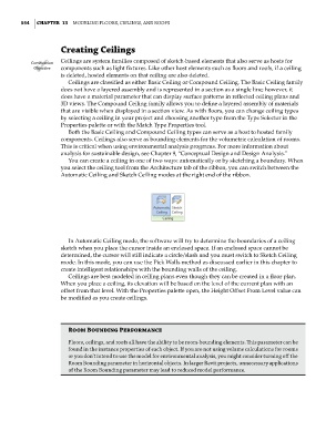
                             You can create a ceiling in one of two ways: automatically or by sketching a boundary. When
                           you select the ceiling tool from the Architecture tab of the ribbon, you can switch between the
                           Automatic Ceiling and Sketch Ceiling modes at the right end of the ribbon.


                             In Automatic Ceiling mode, the software will try to determine the boundaries of a ceiling
                           sketch when you place the cursor inside an enclosed space. If an enclosed space cannot be
                           determined, the cursor will still indicate a circle/slash and you must switch to Sketch Ceiling
                           mode. In this mode, you can use the Pick Walls method as discussed earlier in this chapter to
                           create intelligent relationships with the bounding walls of the ceiling.
                             Ceilings are best modeled in ceiling plans even though they can be created in a floor plan.
                           When you place a ceiling, its elevation will be based on the level of the current plan with an
                           offset from that level. With the Properties palette open, the Height Offset From Level value can
                           be modified as you create ceilings.


                             Room Bounding performance
                             Floors, ceilings, and roofs all have the ability to be room-bounding elements. This parameter can be
                             found in the instance properties of each object. if you are not using volume calculations for rooms
                             or you don’t intend to use the model for environmental analysis, you might consider turning off the
                             room Bounding parameter in horizontal objects. in larger revit projects, unnecessary applications
                             of the room Bounding parameter may lead to reduced model performance.


          c13.indd   554                                                                             05-05-2014   16:57:15

