
Page 592 - Divyank Tyagi
P. 592
558 | ChapTeR 13 Modeling Floors, Ceilings, and rooFs
2. Activate the Level 2 plan; then select the Architecture tab in the ribbon and click Roof ➢
Roof By Footprint.
3. From the Draw panel in the Modify | Create Roof Footprint tab, select the Pick Walls tool
(this should be the default).
4. When you’ve chosen to create a roof by footprint, the Options bar displays the following
settings (change the Overhang value to 1ʹ-0ʺ (300 mm)).
To define whether you want a sloped or flat roof, use the Defines Slope check box in the
Options bar. The Overhang parameter allows you to define the value of the roof overhang
beyond the wall. When the Extend To Wall Core option is checked, the overhang is mea-
sured from the wall core. If the option is deselected, the overhang is measured from the
exterior face of the wall.
5. After defining these settings, place the cursor over one of the walls (don’t click), and
using the Tab key, select all connected walls.
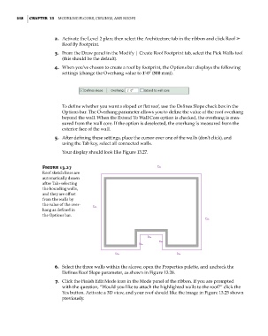
Your display should look like Figure 13.27.
Figure 13.27
roof sketch lines are
automatically drawn
after tab+selecting
the bounding walls,
and they are offset
from the walls by
the value of the over-
hang as defined in
the options bar.
6. Select the three walls within the alcove, open the Properties palette, and uncheck the
Defines Roof Slope parameter, as shown in Figure 13.28.
7. Click the Finish Edit Mode icon in the Mode panel of the ribbon. If you are prompted
with the question, “Would you like to attach the highlighted walls to the roof?” click the
Yes button. Activate a 3D view, and your roof should like the image in Figure 13.25 shown
previously.
c13.indd 558 05-05-2014 16:57:16