
Page 597 - Divyank Tyagi
P. 597
|
Understanding rooF Modeling Methods 563
To create sloped glazing, make a simple pitched roof, select it, and use the Properties palette
to change the type to Sloped Glazing. Once you have done that, activate a 3D view and use the
Curtain Grid tool from the Build panel of the Architecture tab in the ribbon to start applying
horizontal or vertical grids that define the panel sizes; then you can apply mullions using the
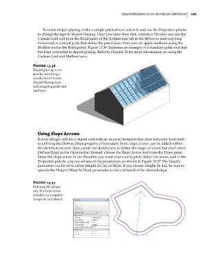
Mullion tool in the Build panel. Figure 13.36 illustrates an example of a standard gable roof that
has been converted to sloped glazing. Refer to Chapter 12 for more information on using the
Curtain Grid and Mullion tools.
Figure 13.36
sloped glazing is cre-
ated by switching a
standard roof to the
sloped glazing type
and assigning grids and
mullions.
Using Slope arrows
If your design calls for a sloped roof with an unusual footprint that does not easily lend itself
to utilizing the Defines Slope property of boundary lines, slope arrows can be added within
the sketch of the roof. First, create the sketch lines to define the shape of a roof, but don’t check
Defines Slope in the Options bar. Instead, choose the Slope Arrow tool from the Draw panel.
Draw the slope arrow in the direction you want your roof to pitch. Select the arrow, and in the
Properties palette, you can set any of the parameters, as shown in Figure 13.37. The Specify
parameter can be set to either Height At Tail or Slope. If you choose Height At Tail, be sure to
specify the Height Offset At Head parameter as the end result of the desired slope.
Figure 13.37
defining the proper-
ties of a slope arrow
added to an irregular
footprint roof sketch
c13.indd 563 05-05-2014 16:57:19