
Page 577 - Divyank Tyagi
P. 577
|
Understanding Floor tYpes 543
4. In the Options bar, specify an offset of 0ʹ-3ʺ (75 mm).
This setting will place the floor boundary just within the inner face of the curtain wall
mullions because the location line of the curtain wall is at the center of the mullions that
are 5ʺ (125 mm) deep.
5. Begin picking the exterior curtain walls by selecting one of the north-south-oriented
walls first.
The first wall that you pick will determine the span direction of the structural floor. You
can change this at any time by picking the Span Direction tool from the Draw panel and
then selecting one of the boundary lines in the floor sketch.
6. Pick the remaining exterior walls to complete the floor boundary.
After you finish defining the boundary lines of the floor, open the Properties palette by
pressing Ctrl+1, typing PP, or clicking the Properties icon at the left end of the ribbon.
7. Click Edit Type in the Properties palette. Select Generic - 12ʺ or Generic - 300 mm as the
active type and click Duplicate. Name the new type Structural Slab.
8. In the Edit Type dialog box, click the Edit button in the Structure row to open the Edit
Assembly dialog box.
9. In the Edit Assembly dialog box, find the layer of the assembly that represents the generic
floor you duplicated. This should be row 2. Change the material of this layer to Concrete
– Cast-In-Place Concrete and change the thickness to 0ʹ-6ʺ (150 mm).
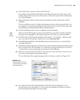
10. Select row 3 and click the Insert button. There should now be four layers. Select the new
row 3 and set its function to Structural Deck [1].
The new Structural Deck properties appear below the layers, as shown in Figure 13.6.
Figure 13.6
setting a layer’s function
to structural deck exposes
additional options.
11. The value for Deck Profile should default to Form Deck_Non-Composite: 2ʹ × 6ʺ or
M_Form Deck_Non-Composite: 50 × 150 mm, but this depends on whether you have a
structural deck profile loaded into your project.
c13.indd 543 05-05-2014 16:57:11