
Page 578 - Divyank Tyagi
P. 578
544 | ChapTeR 13 Modeling Floors, Ceilings, and rooFs
If you don’t have a structural deck profile loaded, finish the floor, select the Insert tab
of the ribbon, and click Load Family. In your default Autodesk content library, find the
Profiles folder and open the Metal Deck subfolder. Pick an appropriate deck pro-
file and click Open to load it. Select the Structural Slab floor and click Edit Type in the
Properties palette to continue the exercise.
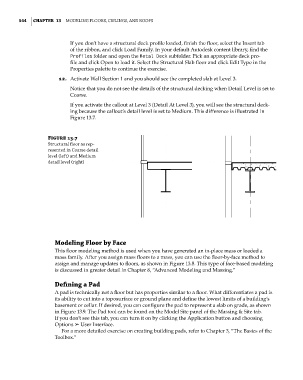
12. Activate Wall Section 1 and you should see the completed slab at Level 3.
Notice that you do not see the details of the structural decking when Detail Level is set to
Coarse.
If you activate the callout at Level 3 (Detail At Level 3), you will see the structural deck-
ing because the callout’s detail level is set to Medium. This difference is illustrated in
Figure 13.7.
Figure 13.7
structural floor as rep-
resented in Coarse detail
level (left) and Medium
detail level (right)
Modeling Floor by Face
This floor modeling method is used when you have generated an in-place mass or loaded a
mass family. After you assign mass floors to a mass, you can use the floor-by-face method to
assign and manage updates to floors, as shown in Figure 13.8. This type of face-based modeling
is discussed in greater detail in Chapter 8, “Advanced Modeling and Massing.”
Defining a pad
A pad is technically not a floor but has properties similar to a floor. What differentiates a pad is
its ability to cut into a toposurface or ground plane and define the lowest limits of a building’s
basement or cellar. If desired, you can configure the pad to represent a slab on grade, as shown
in Figure 13.9. The Pad tool can be found on the Model Site panel of the Massing & Site tab.
If you don’t see this tab, you can turn it on by clicking the Application button and choosing
Options ➢ User Interface.
For a more detailed exercise on creating building pads, refer to Chapter 3, “The Basics of the
Toolbox.”
c13.indd 544 05-05-2014 16:57:11