
Page 275 - Maxwell House
P. 275
Chapter 5 255
Right now we need only the well-known fact from the transmission line theory. Any ideal
transmission line supports the propagation of a harmonic wave () with phase velocity over
said z-axis
() = cos( − ) (5.94)
0
Here and = 2 is the wave magnitude and its propagation coefficient, respectively.
⁄
0
According to (5.94), the wave propagating at distance l acquires phase shift = − and delay
in time = −2 . If is constant over frequency, i.e. there is no dispersion in line, this
⁄
time delay is completely frequency independent. Choosing = cos we can
calculate the required line length = ( /)cos [m] and = −2( )cos [s].
⁄
For example, the typical inter-element distance is around 15 cm at frequency 1GHz ( =
−9
8
30 cm = 0.3m) and = −2(0.3 3 ∙ 10 )cos = 0.628 ∙ 10 cos [] or does not
⁄
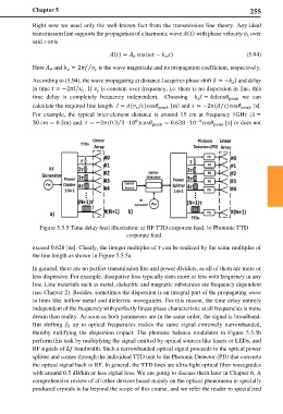
Figure 5.5.5 Time delay feed illustration: a) RF TTD corporate feed, b) Photonic TTD
corporate feed
exceed 0.628 [ns]. Clearly, the integer multiples of can be realized by the same multiples of
the line length as shown in Figure 5.5.5a.
In general, there are no perfect transmission line and power dividers, as all of them are more or
less dispersive. For example, dissipative loss typically rises more or less with frequency in any
line. Line materials such as metal, dielectric and magnetic substances are frequency dependent
(see Chapter 2). Besides, sometimes the dispersion is an integral part of the propagating wave
in lines like hollow metal and dielectric waveguides. For this reason, the time delay entirely
independent of the frequency with perfectly linear phase characteristic at all frequencies is more
dream than reality. As soon as both parameters are in the same order, the signal is broadband.
But shifting up to optical frequencies makes the same signal extremely narrowbanded,
0
thereby nullifying the dispersion impact. The photonic balance modulator in Figure 5.5.5b
perform this task by multiplying the signal emitted by optical sources like lasers or LEDs, and
RF signals of ∆ bandwidth. Such a narrowbanded optical signal proceeds to the optical power
splitter and comes through the individual TTD unit to the Photonic Detector (PD) that converts
the optical signal back to RF. In general, the TTD lines are ultra-light optical fiber waveguides
with around 0.5 dB/km or less signal loss. We are going to discuss them later in Chapter 6. A
comprehensive review of all other devices based mainly on the optical phenomena in specially
produced crystals is far beyond the scope of this course, and we refer the reader to specialized