
Page 272 - Maxwell House
P. 272
252 ANTENNA BASICS
can be suppressed (see Figure 5.4.3b) if a linear array is comprised of unidirectional elements
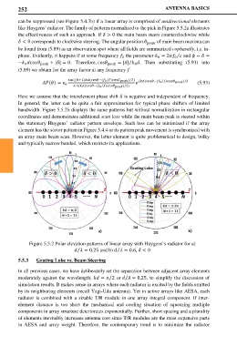
like Huygens’ radiator. The family of patterns normalized to the pick in Figure 5.5.2a illustrates
the effectiveness of such an approach. If > 0 the main beam steers counterclockwise while
< 0 corresponds to clockwise steering. The angular position of main beam maxima can
be found from (5.89) as an observation spot where all fields are summarized cophasally, i.e. in-
⁄
phase. Evidently, it happens if at some frequency the parameter = 2 and − =
0
0
0
⁄
− + || = 0. Therefore, cos = || . Then substituting (5.91) into
0 0
(5.89) we obtain for the array factor at any frequency
sin ((+1)(cos−( 0 )cos )/2) ⁄
⁄
() = 0 (cos−( 0 )cos )/2 (5.93)
⁄
sin ((cos−( 0 )cos )/2)
Here we assume that the interelement phase shift is negative and independent of frequency.
In general, the latter can be quite a fair approximation for typical phase shifters of limited
bandwidth. Figure 5.5.2b displays the same patterns but without normalization in rectangular
coordinates and demonstrates additional scan loss while the main beam peak is steered within
the stationary Huygens’ radiator pattern envelope. Such loss can be minimized if the array
element has the sector pattern in Figure 5.4.4 or its pattern peak movement is synchronized with
an array main beam scan. However, the latter element is quite problematical to design, bulky
and typically narrow banded, which restricts its applications.
Figure 5.5.2 Polar elevation patterns of linear array with Huygens’s radiator for a)
= 0.25 and b) = 0.6, < 0
⁄
⁄
5.5.3 Grating Lobe vs. Beam Steering
In all previous cases, we have deliberately set the separation between adjacent array elements
moderately against the wavelength, = 2 or = 0.25, to simplify the discussion of
⁄
⁄
simulation results. It makes sense in arrays where each radiator is excited by the fields emitted
by its neighboring elements (recall Yagi-Uda antenna). Yet in active arrays like AESA, each
radiator is combined with a sizable T/R module in one array integral component. If inter-
element distance is too short the mechanical and cooling situation of squeezing multiple
components in array structure deteriorates exponentially. Further, short spacing and a plurality
of elements inevitably increases antenna cost since T/R modules are the most expensive parts
in AESA and array weight. Therefore, the contemporary trend is to minimize the radiator