
Page 268 - Maxwell House
P. 268
248 ANTENNA BASICS
beamwidth. Note that = −/4 corresponds to the slow forward wave propagation speed
that is one quarter of light velocity in free space.
= − = − = = −°. Both beams with peaks at = ±60° in elevation cut lean
⁄
⁄
more toward the direction of the forward traveling wave. As a result, they are partially merged
creating plentiful radiation along the z-axis and forming a single beam with the beamwidth close
to 164°. Nevertheless, the directivity slightly increases due to the strong drop in back radiation.
Note that = −/2 corresponds to the forward wave traveling at the half speed of light.
= − = − = = −. °. The two beams are practically fused together forming
⁄
⁄
one wide beam with two shifted peaks at = ±41.4° and strong radiation intensity along the
z-axis. The 3dB beamwidth reduces to 130°. The directivity increases to 5.21 dBi due to
beamwidth reduction and a steady drop in back radiation. Note that = −3/4 corresponds
to the forward wave traveling slightly slower than light.
= − = − = = −°. Finally, two beams are united forming one relatively wide
⁄
beam in the direction = 0° with the 3dB beamwidth of 100.5°. The directivity increases
sharply to 7 dBi due to the beamwidth reduction and steady drop in back radiation. This case
corresponds to a forward wave traveling along array at the speed of light meaning that the phase
shift − = −cos + = (1 − cos) between the far fields created by two adjacent
radiators is equal zero at = 0. Therefore, the far fields radiated by array elements combine
at = 0 in phase creating thereby the main beam peak.
< −. This case corresponds to phase distribution imitating a forward wave with phase
velocity above the speed of light. Clearly, such excitation can be realized by the proper
adjustment of phase shifters in the beamformer shown in Figure 5.4.9c. Looking ahead (see
Chapter 6), note that in the hollow waveguides like a rectangular or circular one the
phenomenon is commonplace and the phase velocity of guided waves exceeds the light speed.
Therefore, they can be used as a natural feed supporting the excitation with > . The family
of array patterns in Figure 5.4.11 illustrates this regime. The number of radiators in the array is
the same as before, i.e. N + 1 = 5. The pattern corresponding to = − or = is the first
in the row. Evidently, the moderate increase in phase velocity above c is quite useful raising
the antenna directivity since the beamwidth narrows much faster than growth in SLL. The
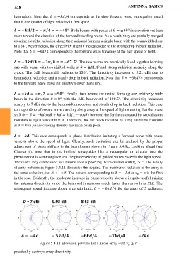
subsequent speed increase above a certain limit, = − 6 4 for the array of 5 radiators,
⁄
Figure 5.4.11 Elevation patterns for a linear array with ≥
practically destroys array directivity.