
Page 264 - Maxwell House
P. 264
244 ANTENNA BASICS
2
cos 0 = ± (5.88)
The reader can verify (5.88) using (5.87). Here M = N + 1 is the total number of radiators in
array, and ≥ 1 is the sequence number of null restricted by cos 0 ≤ 1 or ≤ (2).
⁄
For example, for = the full set of nulls in pattern 2 ≤ , i.e. the net number of sidelobes
does not exceed the number of radiators in the array. Enhancement of separation between
radiators raises the phase difference between fields emitted by the adjacent radiators thereby
shifting the angular position of the first null closer to boresight peak at θ = π/2 and narrowing
the main beam width. The same effect is caused by adding elements in the array. Therefore,
both effects increase the array directivity.
= is located roughly in the middle between two adjacent zeros or = −cos ≅ ∓/2
3
and cos ≅ ∓1/2. Referring to Figure 5.4.7 we can see that the angle is very close to the
3
3
peak of the first sidelobe (blue polygon) at cos = 0.4759 and has according to the blue
3
polygon the relative magnitude ( ) ≅ √2 6 = 0.2357, i.e. SLL = -12.55dB instead of -
⁄
2
12.43dB as displayed in Figure 5.4.7. The estimation is actually quite good.
Roughly speaking, ( ) is the vector sum of the field radiated by the edge array elements
3
(left and right). The
result is remarkable
because it lights the way
to sidelobe level
reduction by tapering or
delivering more power to
the middle elements, i.e.
#2 and #3, then to the
periphery elements, i.e.
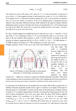
#0 and #5. Plots in
Figure 5.4.8 are
Figure 5.4.8 Patterns of array uniformly excited (green), exemplary. Note that
Chebyshev of -20 dB (blue) and tapered (red) using such simple
approach we almost
reached SLL = -20dB and avoided the complicated Dolph-Chebyshev procedure. These plots
clearly demonstrate that the reduction in SLL is due to the widening the main beam that absorbs
some portion of energy previously contained in sidelobes thereby reducing their level.
In conclusion, let us illustrate how the grating lobes are formed. Recall that a grating lobe is a
sidelobe with peak magnitude slightly lower, equal or sometimes even higher with respect to
the main beam. It is reasonable to assume that the peak of the main beam is formed as shown
in Figure 5.4.7 as in-phase superposition. Evidently, from the phasor diagram point of view, the
same in-phase arrangement may occur once again when the phase shift between adjacent
elements reaches ±2 somewhere in far field area, i.e. it must be, for example, =
−cos = −2 or at the angle cos = /. Since for any real angle
cos ≤ 1, / ≤ 1 or ≥ . Therefore, the grating lobes are natural in arrays when
the spacing between adjaicent elements exceeds the wavelength. It is often desired to keep the