
Page 263 - Maxwell House
P. 263
Chapter 5 243
Here we used the well-known expression for the geometric progression sum and Euler’s
formula associating the trigonometric and complex exponential function: = cos + sin.
We preferred to build the following discussion on the phasor interpretation, not on (5.87)
analysis seeing it as more vivid and understandable. Besides, the phasor diagrams are a very
powerful tool for screening computer model fairness and controlling numerical simulation
results. To interpret the expression (5.86) graphically, we will use a phasor diagram displaying
each term in (5.86) as the vectors of length | | rotated with respect to one another at the angle .
If so, the phasor diagram using traditional rules of vector addition can be built. We specify for
certainty that = or = 0.5 and N = 5 (i.e. 6 radiators in total). The procedure can be
⁄
outlined as:
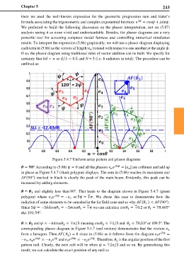
12 = 2
SLL = -12.43dB
Figure 5.4.7 Uniform array pattern and phasor diagrams
= ° According to (5.86) = 0 and all the phasors = | | are collinear and add up
in phase as Figure 5.4.7 (black polygon) displays. The sum in (5.86) reaches its maximum and
(90°) marked in black is clearly the peak of the main beam. Evidently, this peak can be
increased by adding elements.
= and slightly less than 90°. That leads to the diagram shown in Figure 5.4.7 (green
polygon) where 5 = − or 5 = ∓. We chose this case to demonstrate how the
5 0
radiation of some elements to be canceled in the far field zone and so why ( ) < (90°).
1
Since 5 = −5cos = −5cos = ∓ we can calculate cos = ∓0.2 or = 78.465°
1 1 1 1
aka 101.54°.
= and = −cos = ∓/3 meaning cos = ∓1/3 and = 70.53° or 109.5°. The
2
2
2
corresponding phasor diagram in Figure 5.4.7 (red vectors) demonstrates that the vectors
3
form a hexagon. Then ( ) = 0 since in (5.86) as it follows from the diagram =
3
2
− , 4 = − and 5 = − 2 . Therefore, is the angular position of the first
2
2
5
1
0
4
pattern null. Clearly, the next null will be when = ∓2/3 and so on. By generalizing this
result, we can calculate the exact position of any null as