
Page 267 - Maxwell House
P. 267
Chapter 5 247
Note that packaging, cooling, reliability, electrical efficiency, weight, and cost are the dominant
issues of concern for T/R modules since modern communication and radar AESAs comprise
several thousand or even tens of thousands active radiators. Therefore, just a ten dollar reduction
in T/R cost can save a million dollars in overall antenna cost.
5.4.7 Radiation of Linear Array with Progressive Phase Excitation
Let us come back to expression (5.86) assuming for simplicity that | | = , ≥ 0 and the
0
phase shift between two successive radiators is constant, i.e. = , = . ≠ 0. If so,
the array factor in (5.86) can be written in compact form as
() = ∑ (−) = sin ((+1)(−)/2) (−)/2 (5.89)
0 =0 0
⁄
sin ((−) 2)
where = −cos. Here we apply the same expression for a geometric progression sum as
in (5.87). A series of 3D patterns normalized to the peak are put in the top row of Figure 5.4.10
for = ⁄2 , = 0, −⁄4, − /2, −3⁄4, −/2. Note that all these patterns are cut
in half to illustrate the beam shape. Meanwhile, the entire patterns are circularly symmetric
about the z-axis. The polar plots in low row of Figure 5.4.10 represent the set of corresponding
elevation cuts. The bottom line of numbers is the array directivity D normalized to the pattern
peak and calculated using (5.47). The number of radiators + 1 = 5 was chosen to be
relatively low to clearly demonstrate the formation of patterns vs. phase shift between the
radiators.
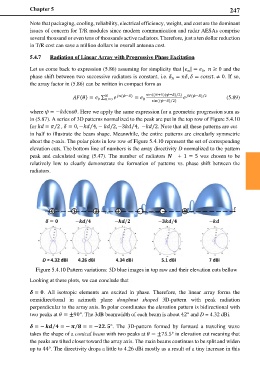
Figure 5.4.10 Pattern variations: 3D blue images in top raw and their elevation cuts bellow
Looking at these plots, we can conclude that
= . All isotropic elements are excited in phase. Therefore, the linear array forms the
omnidirectional in azimuth plane doughnut shaped 3D-pattern with peak radiation
perpendicular to the array axis. In polar coordinates the elevation pattern is bidirectional with
two peaks at = ±90°. The 3dB beamwidth of each beam is about 42° and D = 4.32 dBi.
= − = − = = −. °. The 3D-pattern formed by forward a traveling wave
⁄
⁄
takes the shape of a conical beam with two peaks at = ±75.5° in elevation cut meaning that
the peaks are tilted closer toward the array axis. The main beams continues to be split and widen
up to 44°. The directivity drops a little to 4.26 dBi mostly as a result of a tiny increase in this