
Page 266 - Maxwell House
P. 266
246 ANTENNA BASICS
The typical spacing between the front passive electric dipoles called directors is = 0.1 −
0.15 and ≅ − = −(0.2 − 0.3) < 0. Evidently, the phase of electrical current exerted
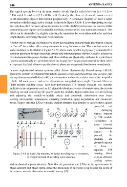
in all succeeding dipoles falls behind progressively. A schematic diagram of such a series
excitation with the single active element is shown in Figure 5.4.9b. It is worth pointing out that
the real phase shift between adjacent currents is a little bit different because the reactive fields
surrounding each dipole (not included in our basic consideration) may and must change it. This
effect can be diminished by slightly adjusting the separation between adjacent dipoles and their
length thereby alternating the near-field structure.
Another way to manage the progressive or any desired phase and amplitude distribution is based
on “brutal” force when all or many elements in array become active. The simplest variant of
such excitation is illustrated in Figure 5.4.9c where each radiator is physically connected to a
common generator through the power divider and individual phase shifters. Usually, all passive
circuit elements like power dividers and phase shifters are physically combined in a joint block
(shown schematically in light blue) called the beamformer. Such a feed network is often called
a corporate feed and allows to get the desired phase and magnitude distribution immediately.
In more sophisticated antenna systems called Active Electronically Steered Arrays (AESA)
each array element is connected through its digitally controlled phase/delay and variable gain
setting element to an individual solid state transmitter and receiver with a Low-Noise Amplifier
(LNA). All such passive and active elements are integrated into a single Transmit / Receive
(T/R) module building block. Each high-performance T/R module typically also includes
multiple extra components such as RF signal distribution systems or beamformers, the circuits
handling out and controlling DC power inside the module, digital calibration circuits tracking
and adjusting the module-to-module phase and amplitude distribution over beam
steering, environment temperature, operating bandwidth, aging degradation, and production
errors. Highly sensitive LNAs typically include elements like limiters to protect them against
powerful and
damaging
signals induced
by T/R module
transmitters or
some external
interference
signals. In
general, the
modules are
grouped together
to form a
separate T/R
Figure 5.4.9 a) Yagi-Uda antenna, b) Series traveling wave excitation, housing block
c) Corporate feed of traveling wave antenna with an efficient
cooling system
and mechanical support structure. Note that all generators and LNAs in the system must be
phase-coherent and phase-stable. Since the discussion of this topic is far beyond the scope of
this course, we refer the reader to a useful survey [10].