
Page 79 - Hot Runner & Control Systems 2020
P. 79
Gate-Mate Hot Sprue Bushings 77
®
Jumbo Gate-Mate Machining Dimensions
®
BUSHING ASSIMBLY
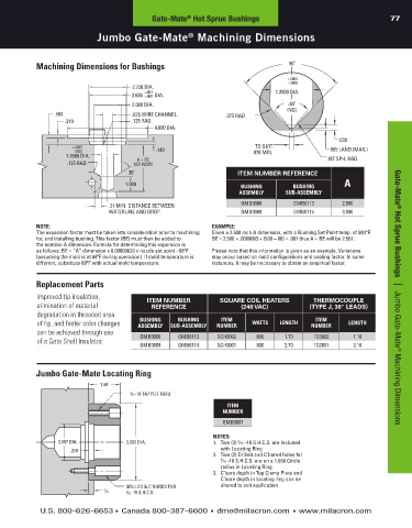
Machining Dimensions for Bushings 90˚
+.0005
–.0000
2.750 DIA.
2.626 +.002 1.2500 DIA.
–.000 DIA.
2.000 DIA. .80˚
INCL
.563 .625 WIRE CHANNEL. .375 RAD.
.219 .125 RAD.
4.000 DIA.
.030
+.0005 TO SUIT .005 LAND (MAX.)
–.0000 .140 .070 MIN.
1.2500 DIA. .187 SPH. RAD.
A + BE
.125 RAD. SEE NOTE
30˚ ITEM NUMBER REFERENCE
1.000 BUSHING BUSHING A
ASSEMBLY SUB-ASSEMBLY
.31 MIN. DISTANCE BETWEEN GMB0008 GMB0113 2.500
WATERLINE AND DROP GMB0009 GMB0114 3.500
NOTE: EXAMPLE:
The expansion factor must be taken into consideration prior to machining Given a 2.500 inch A dimension, with a Bushing Set Point temp. of 500°F:
for, and installing bushing. This factor (BE) must then be added to BE = 2.500 × .0000063 × (500 – 68) = .007 thus A + BE will be 2.507.
the nominal A dimension. Formula for determining this expansion is
as follows: BE = “A” dimension x 0.00000633 x nozzle set point - 68ºF Please note that this information is given as an example. Variations
(assuming the mold is at 68ºF during operation). If mold temperature is may occur based on mold configurations and cooling factor. In some
different, substitute 68ºF with actual mold temperature. instances, it may be necessary to obtain an empirical factor.
Replacement Parts
Improved tip insulation, ITEM NUMBER SQUARE COIL HEATERS THERMOCOUPLE Gate-Mate ® Hot Sprue Bushings | Jumbo Gate-Mate ® Machining Dimensions
elimination of material REFERENCE (240 VAC) (TYPE J, 36" LEADS)
degradation in threaded area
BUSHING
ITEM
BUSHING
ITEM
of tip, and faster color changes ASSEMBLY SUB-ASSEMBLY NUMBER WATTS LENGTH NUMBER LENGTH
can be achieved through use GMB0008 GMB0113 SCH0002 600 1.70 TC0002 1.18
of a Gate Shell Insulator.
GMB0009 GMB0114 SCH0001 800 2.70 TC0001 2.18
Jumbo Gate-Mate Locating Ring
1.50
5 -18 TAPPED THRU
16
ITEM
NUMBER
GMB0007
NOTES:
2.687 DIA. 3.990 DIA. 1. Two (2) ⁄16 -18 S.H.C.S. are included
5
.218 with Locating Ring
2. Two (2) Drilled and C’bored holes for
5 ⁄16 -18 S.H.C.S. are on a 1.656 Circle
radius in Locating Ring
3. C’bore depth in Top Clamp Plate and
C’bore depth in locating ring can be
DRILLED & C'BORED FOR altered to suit application
7
32 -18 S.H.C.S.
5
16
U.S. 800-626-6653 n Canada 800-387-6600 n dme@milacron.com n www.milacron.com