
Page 53 - Die Casting Die Assemblies
P. 53
Die Components – INCH
53
Support Pillars and Stop Pins
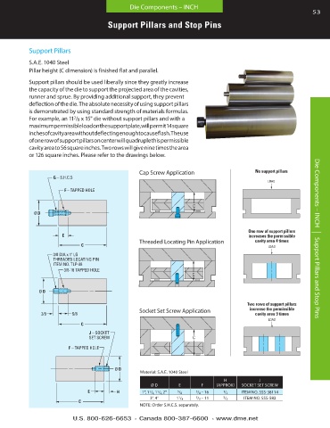
Support Pillars
S .A .E . 1040 Steel
Pillar height (C dimension) is finished flat and parallel .
Support pillars should be used liberally since they greatly increase
the capacity of the die to support the projected area of the cavities,
runner and sprue . By providing additional support, they prevent
deflection of the die . The absolute necessity of using support pillars
is demonstrated by using standard strength of materials formulas .
For example, an 11 /8 x 15" die without support pillars and with a
7
maximum permissible load on the support plate, will permit 14 square
inches of cavity area without deflecting enough to cause flash . The use
of one row of support pillars on center will quadruple this permissible
cavity area to 56 square inches . Two rows will give nine times the area
or 126 square inches . Please refer to the drawings below .
CAP SCREW APPLICATION THREADED LOCATING PIN APPLICATION SOCKET SET SCREW APPLICATION
One row of support pillars Two rows of support pillars
Cap Screw Application No support pillars increases the permissible increase the permissible
G – S.H.C.S 3/8 DIA x 1" LG J – SOCKET cavity area 4 times cavity area 9 times
THREADED LOCATING PIN SET SCREW LOAD LOAD
LOAD
ITEM NO. TLP-38
F – TAPPED HOLE 3/8-16 TAPPED HOLE F – TAPPED HOLE
C
C C
Ø D Ø D Ø D
CAP SCREW APPLICATION THREADED LOCATING PIN APPLICATION SOCKET SET SCREW APPLICATION Two rows of support pillars
One row of support pillars
E 3/8 5/8 No support pillars increases the permissible increase the permissible
H
E
Threaded Locating Pin Application cavity area 4 times Die Components – INCH | Support Pillars and Stop Pins cavity area 9 times
C C LOAD C LOAD LOAD
G – S.H.C.S 3/8 DIA x 1" LG J – SOCKET
THREADED LOCATING PIN SET SCREW
ITEM NO. TLP-38
F – TAPPED HOLE 3/8-16 TAPPED HOLE F – TAPPED HOLE C
C C
Ø D Ø D Ø D
CAP SCREW APPLICATION THREADED LOCATING PIN APPLICATION SOCKET SET SCREW APPLICATION
One row of support pillars Two rows of support pillars
No support pillars increases the permissible increase the permissible
Socket Set Screw Application
E 3/8 5/8 E cavity area 4 times cavity area 9 times
H
LOAD LOAD LOAD
C C C
G – S.H.C.S 3/8 DIA x 1" LG J – SOCKET
THREADED LOCATING PIN SET SCREW C
ITEM NO. TLP-38 C C
F – TAPPED HOLE 3/8-16 TAPPED HOLE F – TAPPED HOLE
Ø D Ø D Ø D
Material: S .A .E . 1040 Steel
H J
Ø D E F (APPROX) SOCKET SET SCREW
E 3/8 5/8 E H 1", 1 / 4, 1 / 2, 2" 5 / 8 3 / 8 – 16 1 / 2 ITEM NO . SSS-38114
1
1
1
3" , 4" 1 / 4 5 / 8 – 11 3 / 8 ITEM NO . SSS-582
C C C
NOTE: Order S .H .C .S . separately .
U.S. 800-626-6653 n Canada 800-387-6600 n www.dme.net