Page 312 - Wago_AutomationTechnology_Volume3_2015_US.pdf
P. 312

750-632

   4    Proportional Valve Module

  310


                                                                750-632
                              750-632
                              13  14
                             1   9
                             2   10
                             3   11
              Status + Error  4  12
                             5   13                                             DI 1             I_lim
                LED 1 ... 16   6  14
                              7  15     Data contacts                           DI 2
                              8  16                                                              I_lim
                                                                1   9
                                                         DI 1           DI 2    L1+
                     DI 1               DI 2                                    L1−
                                                                2  10           L2+
                                                         L1+            L2+     L2−
                     L1+                L2+                                    +24 V            24 V  Logic
                                                                3  11                            3.3 V
                                                         L1−            L2−
                     L1-                L2-                                     0 V
                                                       + 24 V
                                                                                                          Logic
                                                                4  12
                                                                                                 Set
                                                        +24 V                                   Current A
                    +24 V               +24 V                                   B+
                                                                5  13           B−              Temp A
                                                         0 V                                    OCP A
                     0 V                0 V
                                                         0 V                                    Current A
                                                                6  14
                                                         B+             B−
                     B+                 B–                                                      Current B
                                                                                                 Set
                                                                7  15           A+
                                                         A+             A−      A−              Temp B
                     A+                 A–                                                      OCP B
                                                                8  16
                                                        Shield                                  Current B
               Shield (screen)          Shield (screen)  (screen)
                                                                                                         16x
                                        Power jumper contacts
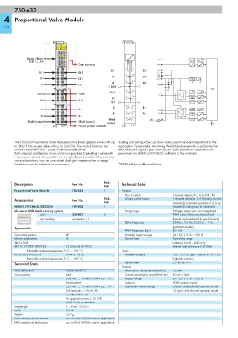
        The 750-632 Proportional Valve Module controls two single-coil valves with up  Scaling and configurable up/down ramps permit set point adjustment to the
        to 24V/1.6A, or one valve with up to 24V/2A. The module features two   application. For example, monitoring threshold value switches is performed via
        current-controlled PWM* outputs with adjustable dither.   two additional digital inputs. Start-up and valve parameters adjustment are
        Both unipolar and bipolar valve control are possible. Operating a valve with   performed via WAGO-I/O-CHECK software or the controller.
        two unipolar coils is also possible via a single-channel module. Characteristic
        curve adaptations, such as zero offset, dual gain compensation or range
        limitations, can be adjusted via parameters.        *PWM = Pulse width modulation
        Description                  Item No.        Pack.    Technical Data
                                                     Unit
        Proportional Valve Module    750-632         1        Outputs
                                                                No. of outputs         2 bipolar outputs (A+, A- and B+, B-)
        Accessories                  Item No.        Pack.      Output current (max.)  1-channel operation: 2 A (Derating must be
                                                     Unit                              observed); 2-channel operation: 1.6 A per
        WAGO-I/O-CHECK, RS-232 kit   759-302         1                                 channel (Derating must be observed)
        Miniature WSB Quick marking system                      Output type            H-bridge output with current-regulated
                     plain           248-501         5                                 PWM output (short-circuit proof and
                     with marking    see Section 11                                    thermal overload-proof for each channel)
                                                                Dither frequency       250 Hz; 125 Hz; 62,5 Hz; ... 1 Hz
        Approvals                                                                      (parameterizable)
                                                                PWM frequency (typ.)   50  kHz
        Conformity marking        1                             Nominal output voltage  24 V DC (-25 % ... +30 %)
        Marine applications       GL                            Type of load           Operating range:
        r UL 508                                                                       inductive (1 mH ... 600 mH);
        4 TÜV 14 ATEX 148929 X    II 3 G Ex nA IIC T4 Gc                               Internal load resistance (> 8 Ohm)
              Permissible ambient temperature 0 °C ... +60 °C  Inputs
        IECEx TUN 14.0035 X       Ex nA IIC T4 Gc               Number of inputs       2 (DI 1, DI 2), Type 1 acc. to IEC 61131;
              Permissible ambient temperature 0 °C ... +60 °C                          high-side switching
        Technical Data                                          Input current          2.7 mA at 24 V
                                                              Module
                                          ®
        Wire connection           CAGE CLAMP  S                 Max. current consumption (internal)  125 mA
        Cross sections            solid:                        Current consumption max. (field side)  20 mA + load
                                  0.08 mm² ... 1.5 mm² / AWG 28 ... 14  Supply voltage  24 V DC (-25 % ... +30 %)
                                  fine-stranded:                Isolation              500 V system/supply
                                  0.25 mm² ... 1.5 mm² / AWG 22 ... 14  Data width process image  6 bytes: single-channel operating mode;
                                  Coil terminals A+/A-/B+/B-:                          12 bytes: dual-channel operating mode
                                  1.5 mm²/AWG 16
                                  For applications acc. to UL 508:
                                  AWG 16 for all terminals
        Strip lengths             8 ... 9 mm / 0.33 in
        Width                     12 mm
        Weight                    53.7 g
        EMC immunity of interference  acc. to EN 61000-6-2, marine applications
        EMC emission of interference  acc. to EN 61000-6-4, marine applications
   307   308   309   310   311   312   313   314   315   316   317