
Page 308 - Wago_AutomationTechnology_Volume3_2015_US.pdf
P. 308
750-673
4 Servo Stepper Controller 55 V / 7.5 A 6IN, 2OUT
306
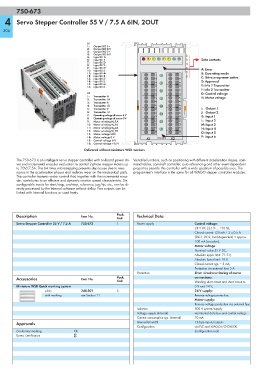
X1
1: Output DO 1+
2: Output DO 0 V
3: Output DO 2+
4: Output DO 0 V
5: Input DI 1+
6: Input DI 1 - A B C D E F G H Data contacts
7: Input DI 2+
8: Input DI 2 -
9: Input DI 3+ A: Error
10: Input DI 3 -
11: Input DI 4+ B: Operating mode
12: Input DI 4 - 1 I 1 C: Drive programm active
13: Input DI 5+ 2 2
14: Input DI 5 - 3 3 D: Approval
15: Input DI 6+ J E: Info 1 Transmitter
16: Input DI 6 - 4 4
5 K 5 F: Info 2 Transmitter
X2 6 6 G: Control voltage
1: Transmitter A
7 L 7 H: Motor voltage
2: Transmitter /A
3: Transmitter B 8 8
4: Transmitter /B 9 M 9
5: Transmitter Z 10 10 I: Output 1
6: Transmitter /Z 11 11 J: Output 2
7: Operating voltage of sensor 5 V N K: Input 1
8: Operating voltage of sensor 0 V 12 12
9: Motor winding M_1A 13 O 13 L: Input 2
10: Motor winding M_1B 14 14 M: Input 3
11: Motor winding M_2A 15 P 15 N: Input 4
12: Motor winding M_2B
13: Motor voltage UDC 16 16 O: Input 5
14: Motor voltage 0 V X1 750-673 X2 P: Input 6
15: Control voltage 0 V
16: Control voltage +24 V
Delivered without miniature WSB markers
The 750-673 is an intelligent servo stepper controller with on-board power dri- Versatile functions, such as positioning with different acceleration slopes, com-
ver and incremental encoder evaluation to control 2-phase stepper motors up mand tables, camshaft controller, auto referencing and other event-dependent
to 70V/7.5A. The 64 times microstepping prevents step losses due to reso- properties provide this controller with a wide spectrum of possible uses. The
nance in the acceleration phases and reduces wear on the mechanical parts. programmer's interface is the same for all WAGO stepper controller modules.
The controller features vector control that, together with the incremental enco-
der, contributes to an efficient and dynamic rotation speed characteristic. Six
configurable inputs for start/stop, end-stop, reference, jog/tip, etc., can be di-
rectly processed by the internal software without delay. Two outputs can be
linked with internal functions or used freely.
Description Item No. Pack. Technical Data
Unit
Servo Stepper Controller 55 V / 7.5 A 750-673 1 Power supply Control voltage:
24 V DC (-25 % ... +30 %),
Closed current 120 mA + 2 x 0.5 A
(DO1, DO2, load-dependent) + approx.
100 mA (encoder);
Motor voltage:
Nominal value 55 V DC,
Absolute upper limit: 71.5 V,
Absolute lower limit: 18 V,
Closed current typ. = 5 mA,
Protection via external fuse 5 A
Protection Short circuit monitoring of motor
Accessories Item No. Pack. connections:
Unit Winding short circuit and short circuit to
Miniature WSB Quick marking system 0 V and 24 V;
plain 248-501 5 24 V supply:
with marking see Section 11 Reverse voltage protection;
Motor supply:
Reverse voltage protection via external fuse
Isolation 500 V system/supply
Voltage supply (internal) via internal data bus and control voltage
Current consumption typ. (internal) 70 mA
Approvals Internal bit width 12-byte inputs/outputs
Configuration via PLC and WAGO-I/O-CHECK
Conformity marking 1 (configuration tool)
Korea Certification