
Page 304 - Wago_AutomationTechnology_Volume3_2015_US.pdf
P. 304
750-670
4 Stepper Controller RS-422 / 24 V / 20 mA
302
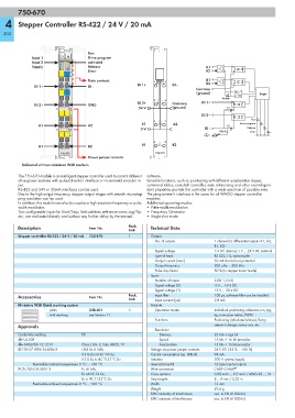
Run
Input 1 13 14 Drive program
Input 2 A E activated
B F
Supply C G Release A1
D H A2
Error
-
Data contacts 1 5 B1
DI 1+ DI - B2
DI 1+ DI -
Common
- (ground) DC Logic
DC
Supply
2 6
DI 2+ Common DI 1+
DI 2+ GND
24 V (ground) E1
DI 2+
Run
3 7
A1 A2 A1 A2 E2 Drive program
0 V DI - Release
10nF Error
4 8
B1 B2 B1 B2
750-670 750-670
Power jumper contacts
Delivered without miniature WSB markers
The 750-670 module is an intelligent stepper controller used to control different software.
drive power sections with pulse/direction interface or incremental encoder in- Versatile functions, such as positioning with different acceleration slopes,
put. command tables, camshaft controller, auto referencing and other event-depen-
RS-422 and 24V or 20mA interfaces can be used. dent properties provide this controller with a wide spectrum of possible uses
Due to the high output frequency, stepper output stages with smooth microstep- The programmer's interface is the same for all WAGO stepper controller
ping resolution can be used. modules.
In addition, this module can also be used as a high-precision frequency or pulse Additional operating modes:
width modulator. •Pulse width modulation
Two configurable inputs for Start/Stop, limit switches, reference cams, Jog/Tip, • Frequency Generator
etc., are evaluated directly and without any further delay by the internal •Single-shot mode
Description Item No. Pack. Technical Data
Unit
Stepper controller RS-422 / 24 V / 20 mA 750-670 1 Outputs
No. of outputs 1 channel (2 differential outputs A1, A2,
B1, B2)
Signal voltage 5 V DC internal, 5 V ... 24 V DC external
Type of load RS 422, TTL, optocoupler
Output current (max.) 30 mA short-circuit protected
Output frequency 200 μHz ... 500 kHz
Pulse duty factor 50 % (in stepper motor mode)
Inputs
Number of inputs 2 (DI 1, DI 2)
Signal voltage (0) -3 V ... +5 V DC
Signal voltage (1) 15 V ... 30 V DC
Accessories Item No. Pack. Input filter 100 μs, software filter can be installed
Unit Input current (typ.) 2.8 mA
Miniature WSB Quick marking system Module
plain 248-501 5 Operation modes Individual positioning, reference run, jog,
with marking see Section 11 tip, instruction tables, PWM
Functions Positioning (absolute/relative), flying
Approvals setpoint change, rotary axis, etc.
Resolution
Conformity marking 1 Distance 23 bits + sign bit
r UL 508 Speed 15 bits + 16 bit prescaler
r ANSI/ISA 12.12.01 Class I, Div. 2, Grp. ABCD, T4 Acceleration 15 bits + 16 bit prescaler
4 TÜV 07 ATEX 554086 X I M2 Ex d I Mb, Voltage via power jumper contacts 24 V DC (-25 % ... +30 %)
II 3 G Ex nA IIC T4 Gc, Current consumption typ. (KBUS) 98 mA
II 3 D Ex tc IIIC T135°C Dc Isolation 500 V system/supply
Permissible ambient temperature 0 °C ... +60 °C Internal bit width 12 byte inputs/outputs
IECEx TUN 09.0001 X Ex d I Mb, Wire connection CAGE CLAMP ®
Ex nA IIC T4 Gc, Cross sections 0.08 mm² ... 2.5 mm² / AWG 28 ... 14
Ex tc IIIC T135°C Dc Strip lengths 8 ... 9 mm / 0.33 in
Permissible ambient temperature 0 °C ... +60 °C Width 12 mm
Weight 49.6 g
EMC immunity of interference acc. to EN 61000-6-2
EMC emission of interference acc. to EN 61000-6-3