Page 300 - Wago_AutomationTechnology_Volume3_2015_US.pdf
P. 300

750-635 / 753-635

   4    Digital Impulse Interface

  298


                         13  14
                         A
             Function        C
                         B
               Error         D
                            —
                          I   I
                                     Data contacts
                                     _                      1    5   _          I
                  I                  I                   I          I           _                         Logic
                                                                                I
                          +  +
                                                                                             2 x 270pF
                                                            2    6

                                     24 V                                     24 V
                                                      24 V
                          —  —                                                               1 x 10nF   Function
                                                            3    7                                        Error

                                     0 V                                       0 V
                                                       0 V                                   2 x 10nF
                            —
                          S  S
                                                                                             2 x 270pF
                                     _                      4    8   _          S
                  S                  S                  S           S           _
                                                                                S
                         750-635                             750-635
                                     Power jumper contacts
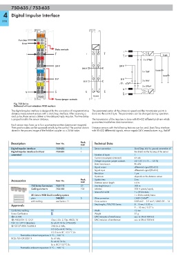
          Fig. 750 Series
          Delivered without miniature WSB markers
        The digital impulse interface is designed for the connection of magnetostrictive  The parameterization of the ultrasonic speed and the transmission points is
        distance measurement sensors with a start/stop interface. After receiving a   done via the control byte. The parameters can be changed during operation.
        read pulse, these sensors deliver a time-delayed reply impulse. The time delay
        is proportional to the sensor distance.             The transmission of the impulses is done with RS-422 differential drivers which
                                                            guarantees trouble-free data transmission.
        Each sensor may have up to four position transmitters (permanent magnets).
        Their position data can be accessed serially by the control. The position data is  Distance sensors with the following features can be used: Start/Stop interface
        stored in the process image of the fieldbus coupler as a 24-bit value.  with RS-422 differential signals, sensor supply 24 V, manufacturer: e.g., Balluff


        Description                  Item No.        Pack.    Technical Data
                                                     Unit
        Digital Impulse Interface    750-635         1        Sensor connection        Start/Stop; Init; Vv; ground connection of
        Digital Impulse Interface (without   753-635  1                                the shield via the housing of the sensor
        connector)                                            Number of inputs         1
                                                              Current consumption (internal)  45 mA
                                                              Voltage via power jumper contacts  24 V DC (-15 % ... +20 %)
                                                              Data transmission        RS 422
                                                              Signal output            differential signal (RS-422)
                                                              Signal input             differential signal (RS-422)
                                                              Resolution               1 μm
                                                              Hysteresis               depends on the distance sensor
        Accessories                  Item No.        Pack.    Update time              2 ms
                                                     Unit     Distance sensor length   ≤ 4 m
                     753 Series Connectors  753-110  25       Line length (max.)       500 m
                     Coding elements  753-150        100      Isolation                500 V system/supply
                                                              Internal bit width       1 x 24 bits data
                     Miniature WSB Quick marking system                                1 x 8 bits control/status
                     plain           248-501         5        Wire connection          CAGE CLAMP ®
                     with marking    see Section 11           Cross sections           0.08 mm² ... 2.5 mm² / AWG 28 ... 14
        Approvals                                             Strip lengths, 750/753 Series  8 ... 9 mm / 0.33 in
                                                                                       9 ... 10 mm / 0.37 in
        Conformity marking        1                           Width                    12 mm
        Korea Certification                                   Weight                   51 g
        r UL 508                                              EMC immunity of interference  acc. to EN 61000-6-2
        r ANSI/ISA 12.12.01       Class I, Div. 2, Grp. ABCD, T4  EMC emission of interference  acc. to EN 61000-6-4
        TÜV 12.1297 X (Brasilien)  Ex nA IIC T4 Gc (750-635)
        4 TÜV 07 ATEX 554086 X    I M2 Ex d I Mb,
                                  II 3 G Ex nA IIC T4 Gc,
                                  II 3 D Ex tc IIIC T135°C Dc
              Permissible ambient temperature 0 °C ... +60 °C
        IECEx TUN 09.0001 X       Ex d I Mb,
                                  Ex nA IIC T4 Gc,
                                  Ex tc IIIC T135°C Dc
              Permissible ambient temperature 0 °C ... +60 °C
   295   296   297   298   299   300   301   302   303   304   305