Page 297 - Wago_AutomationTechnology_Volume3_2015_US.pdf
P. 297

750-630

           SSI Transmitter Interface                                                                               4

                                                                                                                    295


                            13 14
                           A
                 Status        C
                           B
                               D
                           D+ D—
                                       Data contacts                               +D
                                                               1   5
                   +D                  -D                +D           -D
                                                                                         270pF
                            +  +                                                    -D
                                                               2   6

                                       24 V                                       24 V
                                                        24 V
                            —  —                                                             +24V            Logic
                                                                                              +5V
                                                               3   7

                                       0 V                                         0 V                    Status
                                                         0 V
                           CL+  CL—
                                                               4   8
                  +CL                  -CL               +CL          -CL          +CL

                            750-630                            750-630             -CL
                                       Power jumper contacts
            Delivered without miniature WSB markers

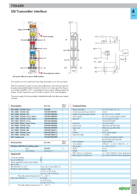
           This module is an SSI interface for the direct connection to an SSI transmitter.
           After the interface has given a clock pulse to the sensor, the interface reads the
           incoming data and transmits it directly in the form of a data word into the pro-
           cess image of the PLC or PC. It is possible to factory adjust different operating
           modes, transfer frequencies and bit widths by means of the control register.
           The power supply for the transmitter is derived internally from the power jumper
           contacts.


           Description                 Item No.        Pack.    Technical Data
                                                       Unit
           SSI/ 24Bit/ 125kHz/ Gray    750-630         1        Sensor connection         In + D, -D / Out + CI, - CI
           SSI/ 24Bit/ 125kHz/ Bin     750-630/000-001  1       Current consumption typ. (internal)  20 mA
           SSI/ 24Bit/ 250kHz/ Bin     750-630/000-002  1       Voltage via power jumper contacts  24 V DC (-15 % ... +20 %)
           SSI/ 24Bit/ 125kHz/ Gray/ Status  750-630/000-004  1  Sensor supply            24 V DC via power jumper contacts
           SSI/ 15Bit/ 125kHz/ Gray/ Status  750-630/000-005  1  Baud rate                125 kHz (max. 250 kHz
           SSI/ 24Bit/ 250kHz/ Gray    750-630/000-006  1                                 750-630/003-000)
           SSI/ 24Bit/ 83kHz/ Gray/ Status  750-630/000-007  1  serial input              32 bits (bit width)
           SSI/ 25Bit/ 125kHz/ Gray    750-630/000-008  1       Signal output             differential signal (RS 422)
           SSI/ 13Bit/ 250kHz/ Bin     750-630/000-009  1       Signal input              differential signal (RS 422)
           SSI/ 25Bit/ 125kHz/ Bin     750-630/000-011  1       Code                      Graycode
           SSI/ 13Bit/ 125kHz/ Gray    750-630/000-012  1       Isolation                 500 V system/supply
           SSI/ 29Bit/ 125kHz/ Bin     750-630/000-013  1       Internal bit width        1 x 32 bits
           SSI/ Configurable           750-630/003-000  1                                 1 x 8 bits control/status (option)
                                                                                          (24 bits data, 8 bits reserved)
           Accessories                 Item No.        Pack.    Wire connection           CAGE CLAMP ®
                                                       Unit     Cross sections            0.08 mm² ... 2.5 mm² / AWG 28 ... 14
           Miniature WSB Quick marking system                   Strip lengths             8 ... 9 mm / 0.33 in
                       plain           248-501         5        Width                     12 mm
                       with marking    see Section 11           Weight                    46.5 g
           Approvals                                            EMC immunity of interference  acc. to EN 61000-6-2, marine applications
                                                                EMC emission of interference  acc. to EN 61000-6-4, marine applications
           Conformity marking       1
           Korea Certification
           Marine applications (versions upon request)  GL
           r UL 508
           r ANSI/ISA 12.12.01      Class I, Div. 2, Grp. ABCD, T4
           4 TÜV 07 ATEX 554086 X   I M2 Ex d I Mb,
                                    II 3 G Ex nA IIC T4 Gc,
                                    II 3 D Ex tc IIIC T135°C Dc
                 Permissible ambient temperature 0 °C ... +60 °C
           IECEx TUN 09.0001 X      Ex d I Mb,
                                    Ex nA IIC T4 Gc,
                                    Ex tc IIIC T135°C Dc
                 Permissible ambient temperature 0 °C ... +60 °C                                                    4.6
   292   293   294   295   296   297   298   299   300   301   302