
Page 294 - Wago_AutomationTechnology_Volume3_2015_US.pdf
P. 294
750-404 / 753-404
4 Up/Down Counter 24 V DC, 100 kHz
292
13 14
Status Status
A
U/D C CLOCK
B
DO 1 D DO 2
U/D CLK
Data contacts
1 5 5 V
U/D CLOCK U/D CLOCK U/D
270pF
+ +
CLOCK
2 6 270pF
24 V 24 V
24 V
— — 10nF U/D Logic
3 7
0 V 0 V
0 V 10nF
A1 A2 CLOCK
270pF
4 8
DO 1 DO 2 DO 1 DO 2 DO DO
750-404 750-404
Power jumper contacts
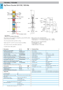
Fig. 750 Series
Delivered without miniature WSB markers
The up/down counter is capable of counting binary pulses of 24VDC and then Differing technical data 750-404/000-003
transmits the data to the fieldbus. • Measuring error < ± 0.2 % (measuring range 0.1 Hz ... 10 kHz)
• Measuring error < ± 1.5 % (measuring range 0.1 Hz ... 100 kHz)
The U/D input allows either Up or Down counting.
Differing technical data 750-404/000-005
Digital outputs DO 1 and DO 2 can be set using the control byte. • Switching rate max. : 5 kHz
• Counter depth: 2 x 16 bits
The counter can be set or reset with the control byte. • Internal bit width: 2 x 16 bits data
A counter lock-out is also possible.
Description Item No. Pack. Technical Data
Unit
Up/Down Counter/100 kHz 750-404 1 No. of outputs 2
Up Counter/Enable Input 750-404/000-001 1 No. of counters 1
Counter with enable input (Gate), U/D input serves as Gate input Current consumption (internal) 70 mA
Peak Time Counter 750-404/000-002 1 Voltage via power jumper contacts 24 V DC (-15 % ... +20 %)
Frequency Counter 0.1 Hz - 100 kHz 750-404/000-003 1 Output current 0.5 A short-circuit protected
Frequency measurement, U/D input serves as Gate input Signal voltage (0) -3 V ... +5 V DC
Up/Down Counter/Switch Output 750-404/000-004 1 Signal voltage (1) 15 V ... 30 V DC
Counter with digital outputs (output switches depending on the count of the counter) Max. switching frequency 100 kHz
2 Up Counter/16 Bit / 5 kHz 750-404/000-005 1 Input current (typ.) 5 mA
U/D input serves as Clock input of the 2nd counter Counter depth 32 bits
Up/Down Counter, 100 Hz (without connector) 753-404 1 Isolation 500 V system/supply
Frequency Counter 0.1 Hz - 100 kHz 753-404/000-003 1 Internal bit width 32 bits data
(without connector) 8 bits control/status
Frequency measurement, U/D input serves as Gate input Wire connection CAGE CLAMP ®
Accessories Item No. Pack. Cross sections 0.08 mm² ... 2.5 mm² / AWG 28 ... 14
Unit Strip lengths, 750/753 Series 8 ... 9 mm / 0.33 in
753 Series Connectors 753-110 25 9 ... 10 mm / 0.37 in
Coding elements 753-150 100 Width 12 mm
Miniature WSB Quick marking system see Section 11 Weight 51 g
Approvals EMC immunity of interference acc. to EN 61000-6-2, marine applications
EMC emission of interference acc. to EN 61000-6-4, marine applications
Conformity marking 1
Korea Certification
Marine applications (versions upon request) ABS, BV, DNV, GL, KR, LR, NKK, PRS, RINA
r UL 508
r ANSI/ISA 12.12.01 Class I, Div. 2, Grp. ABCD, T4
4 TÜV 07 ATEX 554086 X I M2 Ex d I Mb,
II 3 G Ex nA IIC T4 Gc,
II 3 D Ex tc IIIC T135°C Dc
Permissible ambient temperature 0 °C ... +60 °C
IECEx TUN 09.0001 X Ex d I Mb,
Ex nA IIC T4 Gc,
Ex tc IIIC T135°C Dc
Permissible ambient temperature 0 °C ... +60 °C