Page 295 - Wago_AutomationTechnology_Volume3_2015_US.pdf
P. 295

750-638 / 753-638

           2-Channel Up/Down Counter 24 V DC, 500 Hz                                                               4

                                                                                                                    293


                            13  14
                           A
               Function        C       Function
                           B
                  DI 1         D       DI 2
                            13  14
                                       Data contacts
                                                               1   5
                 +DI 1                 +DI 2            +DI 1         +DI 2      +DI
                            +  +
                                                                                            270pF
                                                                                                             Logic
                                                               2   6

                                       24 V                                     24 V
                                                        24 V
                            —  —                                                                              DI
                                                               3   7                                   Function

                                       0 V                                       0 V
                                                         0 V                           10nF
                           15 16
                                                                                            270pF
                                                               4   8
                  -DI 1                -DI 2            -DI 1         -DI 2      -DI
                            750-638                            750-638
                                       Power jumper contacts
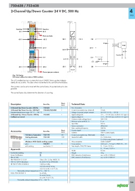
            Fig. 750 Series
            Delivered without miniature WSB markers
           The I/O module has two counters that count 24VDC binary pulses indepen-
           dently of one another. The data is then transmitted to the control via the fieldbus.
           The counters can be set or reset with the control bytes. A counter lock-out is also
           possible.

           The control bytes also determine the direction of counting.


           Description                 Item No.        Pack.    Technical Data
                                                       Unit
           2-Channel Up/Down Counter, 500 Hz  750-638  1        No. of counters           2
           2-Channel Up/Down Counter, 500 Hz/T  750-638/025-000  1  Current consumption typ. (internal)  10 mA
           Extended temperature range: -20 °C ... +60 °C        Voltage via power jumper contacts  24 V DC (-15 % ... +20 %)
           2-Channel Up / Down Counter, 500 Hz   753-638  1     Signal voltage (0)        -3 V ... +5 V DC (acc. to EN 61131 type 1)
           (without connector)                                  Signal voltage (1)        15 V ... 30 V DC (acc. to EN 61131 type 1)
                                                                Common mode voltage (max.)  500 V DC
                                                                Minimum pulse width (0, 1)   1  ms
                                                                Input filter              0.2 ms
                                                                Sensor connection         differential
                                                                Max. switching frequency  500 Hz
           Accessories                 Item No.        Pack.    Counter depth             16 bits
                                                       Unit     Isolation                 500 V system/supply
                       753 Series Connectors  753-110  25       Current consumption typ. (field side)  8 mA
                       Coding elements  753-150        100      Internal bit width        2 x 16 bits data
                                                                                          2 x 8 bits control/status (optional)
                       Miniature WSB Quick marking system       Wire connection           CAGE CLAMP ®
                       plain           248-501         5        Cross sections            0.08 mm² ... 2.5 mm² / AWG 28 ... 14
                       with marking    see Section 11           Strip lengths, 750/753 Series  8 ... 9 mm / 0.33 in
           Approvals                                                                      9 ... 10 mm / 0.37 in
                                                                Width                     12 mm
           Conformity marking       1                           Weight                    58 g
           Korea Certification                                  EMC immunity of interference  acc. to EN 61000-6-2
           r UL 508                                             EMC emission of interference  acc. to EN 61000-6-4
           r ANSI/ISA 12.12.01      Class I, Div. 2, Grp. ABCD, T4
           TÜV 12.1297 X (Brasilien)  Ex nA IIC T4 Gc (750-638)
           4 TÜV 07 ATEX 554086 X   I M2 Ex d I Mb,
                                    II 3 G Ex nA IIC T4 Gc,
                                    II 3 D Ex tc IIIC T135°C Dc
                 Permissible ambient temperature 0 °C ... +60 °C
           IECEx TUN 09.0001 X      Ex d I Mb,
                                    Ex nA IIC T4 Gc,
                                    Ex tc IIIC T135°C Dc
                 Permissible ambient temperature 0 °C ... +60 °C
                                                                                                                    4.6
   290   291   292   293   294   295   296   297   298   299   300