
Page 299 - Wago_AutomationTechnology_Volume3_2015_US.pdf
P. 299
750-637
Incremental Encoder Interface 4
297
13 14 15 16
A A C A C Ref
B B B Gate 24V V
C D D N 2 DC e
Latch A A — + — N 1 DC
Data contacts 0V V 0
_ 1 5 1 5
A
__ 0 V A/A 24V/ A B C
A — 24 V 0V _ _ _
B B N1 N2
A B C
A,B,C
_ 2 6 2 6
B
__ N 2 B/B N1/ N1/
B N 1 N2 N2 Logic
C C — L G Latch N1/N2
_ 3 7 3 7
__ Gate C/C Latch/ Gate/ Gate/Ref
C
C Latch Gate Ref
U U R S DC Latch
e 0
Sensor DC
supply 4 8 4 8
5 V Shield (screen) V /V 0 Ref/ Shield
e
0 V Ref Shield (screen)
750-637 750-637
(screen)
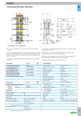
Delivered without miniature WSB markers
This module is an interface for any incremental encoder with an RS-422 A counter lock-out is possible using input G. Input “Ref“ can be used to activate
connection. the initial point “C“ function.
A counter with quadrature decoder as well as a latch for the zero impulse can The cam outputs N1 and N2 indicate whether the counter value is within a
be read or enabled by the control. The control can set the counter or transmit defined range of values. The range can be adjusted.
the counter value to the Latch. As an alternative this can also be done using
input “C” or “Latch”. The module must be powered using an external 24VDC power supply, from
which power to the transmitter (Ue, U1) can also be derived.
The frequency data is automatically acquired and can also be transmitted to
the control. The shield (screen) is directly connected to the DIN rail.
Description Item No. Pack. Technical Data
Unit
Incremental Encoder Interface 750-637 1 Sensor connection A, A/, B, B/, C, C/
Incremental Encoder Interface 750-637/000-001 1 Current consumption (internal) 110 mA
24 V/32 Bit differential Counter 32 bits binary
Incremental Encoder Interface 750-637/000-002 1 Max. operating frequency 250 kHz
24 V/32 Bit single ended Quadrature decoder 4-fold report
Inkremental-Encoder-Interface 750-637/000-003 1 Zero impulse latch 32 bits
RS422/32Bit/Single Interpreter Commands read, set, enable
Incremental Encoder Interface 750-637/000-004 1 Power supply 24 V DC (-15 % ... +20 %)
24 V/32 Bit single ended/cam outputs Current consumption (typ.) 35 mA without load
Operating voltage of sensor 5 VDC
Sensor max. output current 300 mA
Internal bit width 1 x 32 bits data
Accessories Item No. Pack. 1 x 8 bits control/status
Unit Digital outputs (N1, N2)
Miniature WSB Quick marking system Output voltage 24 V DC
plain 248-501 5 Output current (max.) 0.5 A short-circuit protected
with marking see Section 11 Digital inputs (Latch, Gate, Ref)
Signal voltage (0) -3 V ... +5 V DC
Approvals Signal voltage (1) 15 V ... 30 V DC
Input current (typ.) Latch 5 mA, Gate 7 mA, Ref. 7 mA
Conformity marking 1 Wire connection CAGE CLAMP ®
Korea Certification Cross sections 0.08 mm² ... 2.5 mm² / AWG 28 ... 14
Marine applications (versions upon request) ABS, BV, DNV, GL, KR, LR, NKK, PRS, RINA Strip lengths 8 ... 9 mm / 0.33 in
r UL 508 Width 24 mm
r ANSI/ISA 12.12.01 Class I, Div. 2, Grp. ABCD, T4 Weight 103.3 g
TÜV 12.1297 X (Brasilien) Ex nA IIC T4 Gc (750-637) EMC immunity of interference acc. to EN 61000-6-2, marine applications
4 TÜV 07 ATEX 554086 X I M2 Ex d I Mb, EMC emission of interference acc. to EN 61000-6-4, marine applications
II 3 G Ex nA IIC T4 Gc,
II 3 D Ex tc IIIC T135°C Dc
Permissible ambient temperature 0 °C ... +60 °C
IECEx TUN 09.0001 X Ex d I Mb,
Ex nA IIC T4 Gc,
Ex tc IIIC T135°C Dc
Permissible ambient temperature 0 °C ... +60 °C 4.6