
Page 305 - Wago_AutomationTechnology_Volume3_2015_US.pdf
P. 305
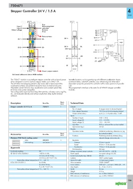
750-671

           Stepper Controller 24 V / 1.5 A                                                                         4

                                                                                                                    303


                                       Run
                Input 1     13 14      Drive programm
                Input 2    A   E       activated
            Driver voltage  B C  F G   Release                                        A1
                           D   H       Error                                          A2      Logic
                              -                                                       B1
                                                                                      B2
                                       Data contacts             1    5
                                                           DI 1+         DI -        24 V
                 DI 1+                 DI -
                                                                                      0 V
                              -                                                                             Logic
                                                                 2    6              DI 1+
                                                           DI 2+         DI -
                 DI 2+                 DI -                                                    E1
                                                           24 V
                                                                                      DI -
                                                                                     DI 2+
                                                                                                         Run
                                                                 3    7
                   A1                  A2                   A1           A2                    E2   Drive program
                                                            0 V                       DI -             Release
                                                                                            10nF        Error
                                                                 4    8
                   B1                  B2                    B1          B2
                            750-671                               750-671
                                       Power jumper contacts
            Delivered without miniature WSB markers

           The 750-671 module is an intelligent stepper controller with on-board power   Versatile functions, such as positioning with different acceleration slopes,
           driver designed to control 2-phase stepper motors up to 24V/1.5A.  command tables, camshaft controller, auto referencing and other event-
           The 64 times microstepping prevents step losses due to resonance in the   dependent properties provide this controller with a wide spectrum of possible
           acceleration phases and prevents excessive wear on mechanical parts.   uses
           Adjustable current limits for stop, acceleration and constant speed help   The programmer's interface is the same for all WAGO stepper controller
           minimize motor power dissipation.                   modules.
           Two configurable inputs for Start/Stop, limit switches, reference cams, Jog/Tip,
           etc., are evaluated directly and without any further delay by the internal
           software.


           Description                 Item No.        Pack.    Technical Data
                                                       Unit
           Stepper controller 24 V/1.5 A  750-671      1        Outputs
                                                                  No. of outputs          1 stepper motor (2 phases/bipolar)
                                                                  Max. stepper frequency  7812 Hz at 64 microstepping internal
                                                                  Output current (max.)   up to 2 x 1.5 A peak value; 1 A eff.
                                                                Inputs
                                                                  Number of inputs        2 (DI 1, DI 2)
                                                                  Signal voltage (0)      -3 V ... +5 V DC
                                                                  Signal voltage (1)      15 V ... 30 V DC
                                                                  Input filter            100 μs, software filter can be installed
                                                                  Input current (typ.)    2.8 mA
                                                                Module
                                                                  Operation modes         Individual positioning, reference run, jog,
           Accessories                 Item No.        Pack.                              tip, instruction tables
                                                       Unit       Functions               Positioning (absolute/relative), flying
           Miniature WSB Quick marking system                                             setpoint change, rotary axis, etc.
                       plain           248-501         5          Resolution
                       with marking    see Section 11               Distance              23 bits + sign bit
                                                                    Speed                 15 bits + 16 bit prescaler
           Approvals                                                Acceleration          15 bits + 16 bit prescaler
                                                                  Microstepping           64 steps
           Conformity marking       1                           Voltage via power jumper contacts  24 V DC (-25 % ... +30 %)
           4 TÜV 07 ATEX 554086 X   I M2 Ex d I Mb,             Power supply              via system voltage DC/DC
                                    II 3 G Ex nA IIC T4 Gc,     Current consumption typ. (KBUS)  85 mA
                                    II 3 D Ex tc IIIC T135°C Dc  Isolation                500 V system/supply
                 Permissible ambient temperature 0 °C ... +60 °C  Internal bit width      12 byte inputs/outputs
           IECEx TUN 09.0001 X      Ex d I Mb,                  Wire connection           CAGE CLAMP ®
                                    Ex nA IIC T4 Gc,            Cross sections            0.08 mm² ... 2.5 mm² / AWG 28 ... 14
                                    Ex tc IIIC T135°C Dc        Strip lengths             8 ... 9 mm / 0.33 in
                 Permissible ambient temperature 0 °C ... +60 °C  Width                   12 mm
                                                                Weight                    51.8 g
                                                                EMC immunity of interference  acc. to EN 61000-6-2
                                                                EMC emission of interference  acc. to EN 61000-6-3
                                                                                                                    4.6