
Page 309 - Wago_AutomationTechnology_Volume3_2015_US.pdf
P. 309
4
307
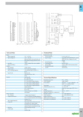
DI (1 ... 6)+
DI (1 ... 6) -
K ... P
DO 1+
I
DO 0 V
X1 X2
1: DO 1+ 1 1 1: A DO 2+ J
2: DO 0 V 2 2 2: /A DO 0 V
3: DO 2+ 3 3 3: B
4: DO 0 V 4 4 4: /B
5: DI 1+ 5 5 5: C
M_1A
6: DI 1 - 6 6 6: /C
7: DI 2+ 7 7 7: 5 V M_1B Logic Logic
M_2A
8: DI 2 - 8 8 8: GND M_2B
9: DI 3+ 9 9 9: M_1A
10: DI 3 - 10 10 10: M_1B
11: DI 4+ 11 11 11: M_2A 5 V
12: DI 4 - 12 12 12: M_2B 0 V A B C D
13: DI 5+ 13 13 13: UDC E F
14: DI 5 - 14 14 14: 0 V
15: DI 6+ 15 15 15: 0 V
16: DI 6 - 16 16 16: 24 V
X1 X2 H
750-673 G A, B, C
A, B, C
70 V 24 V 0 V
UDC
Technical Data Technical Data
Inputs Incremental encoder
Signal voltage (0) -3 V ... +5 V DC Sensor connection A, /A, B, /B, C, /C
Signal voltage (1) 15 V ... 30 V DC Signal voltage Compatible with RS-485/RS-422, common
Electrical isolation from each other and GND with motor voltage and control
from all other voltage potentials on the voltage
module Sensor frequency 1 MHz
Input filter 100 μs, software filter can be installed Terminating resistor internal 120 Ω
Input current (typ.) 2.8 mA Sensor supply 5 V DC, 300 mA short-circuit protected
Outputs Quadrature decoder 4-fold report
No. of outputs 2 (DO1, DO2) Counter 32 bits binary
Output current 0.5 A, short-circuit protected
Max. switching frequency 5 Hz, inductive load to IEC947-5-1,
DC13
Type of load Resistive load,
inductive load (max. 2H),
lamps
Function Inputs (preset): General Specifications
DI 1: Drive stop,
DI 2: Reference input, Operating temperature 0°C ... +55°C
DI 3: Jog switch in positive direction, Wire connection CAGE CLAMP ®
DI 4: Jog switch in negative direction, Cross sections 0.08 mm² ... 1.5 mm² / AWG 28 ... 14
DI 5: Limit switch in positive direction, AWG 12 /14: THHN, THWN
DI 6: Limit switch in negative direction, Strip lengths 5 ... 6 mm / 0.22 in
Outputs (preset): Dimensions (mm) W x H x L 51 x 70 x 100
DO 1: Target reached, Height from upper-edge of DIN 35 rail
DO 2: Error, Weight 56 g
Inputs and outputs can be freely Storage temperature -25 °C ... +85 °C
reconfigured. Relative air humidity (no condensation) 95 %
Motor connection Vibration resistance acc. to IEC 60068-2-6
No. of outputs 1 stepper motor (2 phases) Shock resistance acc. to IEC 60068-2-27/29
Output current (max.) 2 x 7.5 A temporary; derating starting at Degree of protection IP20
50 °C; 2 x 5.0 A nominal current; derating EMC immunity of interference acc. to EN 61000-6-2
starting at 50 °C EMC emission of interference acc. to EN 61000-6-3
Max. stepper frequency 7812 Hz full step
Diagnostics Short circuit or ground fault overcurrent,
overtemperature, supply voltage
monitoring, motor wire break, wrong
rotational direction incremental encoder -
Resolution 64 microsteps per full step
Cable length 30 m
shielded cable
4.6