
Page 386 - Wago_AutomationTechnology_Volume3_2015_US.pdf
P. 386
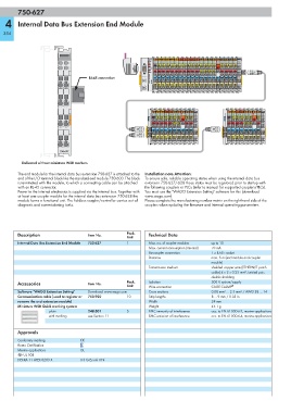
750-627

   4    Internal Data Bus Extension End Module

  384


                         A
                             C
                         B
                             D
                                     RJ-45 connection


                         750-627

          Delivered without miniature WSB markers

        The end module for the internal data bus extension 750-627 is attached to the  Installation note Attention:
        end of the I/O terminal block like the standard end module 750-600. The block  To ensure safe, reliable operating states when using the internal data bus
        is terminated with the module, to which a connecting cable can be attached   extension 750-627/-628 these states must be registered prior to startup with
        with an RJ-45 connector.                            the following couplers or PLCs (refer to manual for supported couplers/PLCs).
        Power to the internal electronics is supplied via the internal bus. Together with   You must use the "WAGO Extension Setting" software for this (download:
        at least one coupler module for the internal data bus extension 750-628 the   www.wago.com).
        module forms a functional unit. The fieldbus coupler/controller carries out all   Please complete the manufacturing number matrix on the right-hand side of the
        diagnosis and commissioning tasks.                  couplers when updating the firmware and internal operating parameters.


        Description                  Item No.        Pack.    Technical Data
                                                     Unit
        Internal Data Bus Extension End Module  750-627  1    Max. no. of coupler modules  up to 10
                                                              Max. current consumption (internal)  70 mA
                                                              Buscoupler connection    1 x RJ-45 socket
                                                              Distance                 max. 5 m (end module and coupler
                                                                                       module)
                                                              Transmission medium      shielded copper wire (ETHERNET patch
                                                                                       cable) 4 x 2 x 0.25 mm², twisted pair,
                                                                                       double shielding
        Accessories                  Item No.        Pack.    Isolation                500 V system/supply
                                                     Unit     Wire connection          CAGE CLAMP ®
        Software "WAGO Extension Setting"  Download: www.wago.com  Cross sections      0.08 mm² ... 2.5 mm² / AWG 28 ... 14
        Communication cable (used to register or   750-920  10  Strip lengths          8 ... 9 mm / 0.33 in
        remove the end extension module)                      Width                    24 mm
        Miniature WSB Quick marking system                    Weight                   45.1 g
                     plain           248-501         5        EMC immunity of interference  acc. to EN 61000-6-2, marine applications
                     with marking    see Section 11           EMC emission of interference  acc. to EN 61000-6-4, marine applications


        Approvals
        Conformity marking        1
        Korea Certification
        Marine applications       GL
        r UL 508
        DEKRA 11 ATEX 0203 X      II 3 G Ex nA II T4