Page 388 - Wago_AutomationTechnology_Volume3_2015_US.pdf
P. 388

750-622

   4    Binary Spacer Module

  386   with supply module
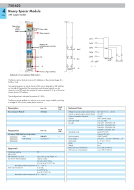


            Operating    13  14
               mode      A
              Input/     B   C      Data width
              output         D
                                    Data contacts
                                                            1    5
                                                                                DIP 1
                          +  +
                                                                                DIP 2
                                    Supply via
                                    power jumper contacts   2     6

                                    24 V                                        DIP 3         Logic
                                                                     24 V
                          —  —
                                                                                DIP 4
                                                            3    7

                                    0 V                                         DIP 5
                                                                     0 V                      Operating
                                                                                                 mode
                                                                                                        Data width

                                                            4    8

                         750-622                             750-622
                                    Power jumper contacts

          Delivered without miniature WSB markers
        The binary spacer module reserves bit addresses in the process image of a
        fieldbus node.
        The operating mode as well as the bit width can be adjusted by DIP switches
        on the side of the module. The operating mode (inputs/outputs) can be
        chosen by one DIP switch, the number of inputs or outputs (2, 4, 6 or 8) can be
        chosen by two DIP switches.
        The configuration is indicated by means of 3 LEDs.
        The binary spacer module can also act as a power supply module, providing
        a voltage of 24V via the power jumper contacts.

        Description                  Item No.        Pack.    Technical Data
                                                     Unit
        Binary Spacer Module         750-622         1        Voltage via power jumper contacts (max.)  24 V DC (-15 % ... +20 %)
                                                              Current via power jumper contacts (max.)  10 A DC
                                                              Current consumption (internal)  10 mA
                                                              Isolation                500 V system/supply
                                                              Internal bit width       2, 4, 6 or 8 Bit
                                                              Bit width                2 Bit: DIP1: OFF/DIP2: OFF;
                                                                                       4 Bit: DIP1: ON/DIP2: OFF ;
                                                                                       6 Bit: DIP1: OFF/DIP2: ON ;
        Accessories                  Item No.        Pack.                             8 Bit DIP1: ON/DIP2: ON
                                                     Unit     Operating mode           Inputs DIP 3 OFF ;
        Miniature WSB Quick marking system                                             Outputs DIP 3 ON
                     plain           248-501         5        Wire connection          CAGE CLAMP ®
                     with marking    see Section 11           Cross sections           0.08 mm² ... 2.5 mm² / AWG 28 ... 14
                                                              Strip lengths            8 ... 9 mm / 0.33 in
                                                              Width                    12 mm
                                                              Weight                   48 g
        Approvals                                             EMC immunity of interference  acc. to EN 61000-6-2
                                                              EMC emission of interference  acc. to EN 61000-6-4
        Conformity marking        1
        r UL 508
        r ANSI/ISA 12.12.01       Class I, Div. 2, Grp. ABCD, T4
        4 TÜV 07 ATEX 554086 X    I M2 Ex d I Mb,
                                  II 3 G Ex nA IIC T4 Gc,
                                  II 3 D Ex tc IIIC T135°C Dc
              Permissible ambient temperature 0 °C ... +60 °C
        IECEx TUN 09.0001 X       Ex d I Mb,
                                  Ex nA IIC T4 Gc,
                                  Ex tc IIIC T135°C Dc
              Permissible ambient temperature 0 °C ... +60 °C
   383   384   385   386   387   388   389   390   391   392   393