
Page 387 - Wago_AutomationTechnology_Volume3_2015_US.pdf
P. 387
750-628
Internal Data Bus Extension Coupler Module 4
385
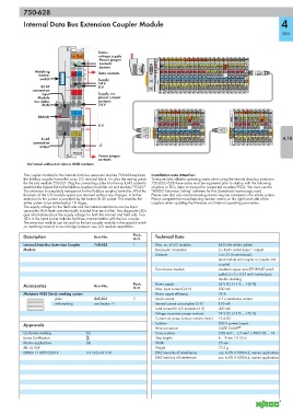
Status
01 02 voltage supply
-Power jumper
A
C contacts
B -System
D
Matching Data contacts
resistor 24V 0V
switch Supply
24 V
RJ 45 0 V
connection
input + + Supply via
Module power jumper
bus status contacts
RUN 24 V
— —
ERROR
0 V
RJ-45 4.10
connection
output
750-628
Power jumper
contacts
Delivered without miniature WSB markers
The coupler module for the internal data bus extension module 750-628 replaces Installation note Attention:
the fieldbus coupler/controller at an I/O terminal block. It is also the mating piece To ensure safe, reliable operating states when using the internal data bus extension
for the end module 750-627. Plug the connecting cable into the top RJ-45 socket to 750-627/-628 these states must be registered prior to startup with the following
establish the logical link to the fieldbus coupler/controller via end module 750-627. couplers or PLCs (refer to manual for supported couplers/PLCs). You must use the
The extension is completely transparent for the fieldbus coupler/controller. All of the "WAGO Extension Setting" software for this (download: www.wago.com).
functions of the I/O module system are retained without any changes. A further Please note that only one terminating resistor may be activated in the whole system.
extension to the system is provided by the bottom RJ-45 socket. This enables the Please complete the manufacturing number matrix on the right-hand side of the
entire system to be extended by 10 stages. couplers when updating the firmware and internal operating parameters.
The supply voltage for the field side and the internal electronics can be input
separately. Both levels are electrically isolated from each other. Two diagnostic LEDs
give information about the supply voltage for both the internal and field side. Two
LEDs in the input socket indicate fault-free communication with the bus coupler.
The extension module can be used as the last coupler module in the system (switch
on matching resistor) or as a bridge between two I/O module assemblies.
Description Item No. Pack. Technical Data
Unit
Internal Data Bus Extension Coupler 750-628 1 Max. no. of I/O modules 64 (in the whole system)
Module Buscoupler connection 2 x RJ-45 socket (input + output)
Distance 5 m (10 m see manual),
(end module and coupler or coupler and
coupler)
Transmission medium shielded copper wire (ETHERNET patch
cable) 4 x 2 x 0.25 mm², twisted pair,
double shielding
Accessories Item No. Pack. Power supply 24 V DC (-15 % ... +20 %)
Unit Max. input current (24 V) 200 mA
Miniature WSB Quick marking system Power supply efficiency 76 %
plain 248-501 5 Inrush current 2.5 x continuous current
with marking see Section 11 Internal current consumption (5 V) 150 mA
Total current for I/O modules (5 V) 400 mA
Voltage via power jumper contacts 24 V DC (-15 % ... +20 %)
Current via power jumper contacts (max.) 10 A DC
Approvals Isolation 500 V system/supply
Wire connection CAGE CLAMP ®
Conformity marking 1 Cross sections 0.08 mm² ... 2.5 mm² / AWG 28 ... 14
Korea Certification Strip lengths 8 ... 9 mm / 0.33 in
Marine applications GL Width 25 mm
r UL 508 Weight 75.2 g
DEKRA 11 ATEX 0203 X II 3 G Ex nA II T4 EMC immunity of interference acc. to EN 61000-6-2, marine applications
EMC emission of interference acc. to EN 61000-6-4, marine applications