
Page 461 - Wago_AutomationTechnology_Volume3_2015_US.pdf
P. 461
6
459
System bus 1: RD+/TD+
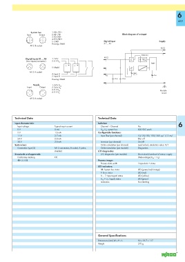
Input Output 2: RD--/TD-- Block diagram of an input
3: TD--/RD--
4: TD+/RD+
5: GND Digital Input Supply
Housing: Shield X1 ... X4
M12 B coded
M12
Diagnostics
M12
Digital Inputs X1 ... X4 1: 24 V
(two intputs/connector) 3: 0 V U
LS
Logic
5 5
5: Shield
M12 A coded
4: Input A Input
0 ... 7
2: Input B Error
Housing: Shield 270 pF 270 pF
Supply 1: 24 V U 5
Input Output 2: 24 V U LS
3: 0 V U A Module
4: 0 V U LS
A mount
M12 A coded
Technical Data Technical Data
Input characteristic: Isolation: 6
Input voltage Typical input current Channel – Channel No
0 V 0 mA U LS , U A , system bus 500 VDC each
5 V 1.6 mA Configurable functions:
11 V 2.7 mA Input filter (per channel) 10/ 25/ 50/ 100/ 200 μs/ 1/ 3 ms/
24 V 2.8 mA filter off
30 V 2.8 mA Inversion (per channel) On/off
System bus: Online simulation (per channel) Lock/unlock, simulation value: 0/1
Connection type (3) M12 connectors, B coded, 5 poles, Online simulation (per module) Diagnostics
shielded I/O diagnostics:
Standards and approvals: I/O diagnostics (per module) Short circuit/overload of sensor supply
Conformity marking 1 Undervoltage (U LS + U A )
r UL 508 Process image:
Process data width 1-byte data + status
LED indicators:
SB: System bus status LED (green/red/orange)
F: Error status LED (red)
0 ... 7: Input signal status LED (yellow)
U LS + U A : Supply status LED (green)
Indicators Non-latching
General Specifications
Dimensions (mm) W x H x L 50 x 35.7 x 117
Weight 270 g