
Page 462 - Wago_AutomationTechnology_Volume3_2015_US.pdf
P. 462
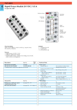
767-4801

   6    Digital Output Module 24 V DC / 0.5 A

  460   8 outputs (8 x M8)


                                                                                     8DO
                                                           Module marking
                                                                                             System bus
                                                                                             output (3)
                                                              System bus
                                                                input (3)
                                                                                          X
                                                                                    7
                                                                                          8
                                                             LED indicators
                                                                        X
                                                                        7     6
                                                                                          X
                                                                                    5
                                                                                          6
                                                                                             Digital
                                                                        X
                                                                        5     4              outputs (2)
                                                                                          X
                                                                                    3
                                                                                          4
                                                                        X                    Channel
                                                                        3     2              marking
                                                                                          X
                                                                                    1        (1 field for each
                                                                                          2
                                                                                             port/channel)
                                                                        X
                                                                        1     0
                                                                                             Supply
                                                                                24 V
                                                                                U  U         output (1)
                                                                                 LS  A
                                                                 Supply        767-4801
                                                                input (1)
        Short description:                                  Included:
        Digital output module for actuator control (e.g., magnetic valves,   • 1 x WMB marker, red
        DC contactors, indicators).                         • 1 x marking strip
                                                            •2 x M8 protective cap
        Features:
        • 8 digital outputs, 24 VDC / 0.5 A
        • Diagnostic capable (per channel)
        • Parametrizable (inversion, substitute value strategy, manual mode,
          online simulation and diagnostics)


        Description                  Item No.        Pack.    Technical Data
                                                     Unit
        8DO 24V DC 0.5A (8xM8)       767-4801        1        Module supply:
        8DO 24V DC 0.5A IF (8xM8)*   767-4801/000-800  1        Connection type (1)    M12 connectors, A coded, 4 poles;
        * Interference-free for safety function applications (see manual)              Derating must be observed
                                                                Current carrying capacity of supply
                                                                connections            Max. 8 A (U LS : 4 A, U A : 4 A)
                                                                Supply voltage
                                                                                       24 V DC (-25 % ... +30 %)
                                                                 Logic and sensor voltage U LS
                                                                                       24 V DC (-25 % ... +30 %)
                                                                 Actuator voltage U A
                                                                Supply current
                                                                                       typ. 45 mA (only logic part)
                                                                 Logic and sensor current I LS
                                                                                       typ. 25 mA + actuators
                                                                 Actuator current I A
                                                                Protection             Reverse voltage protection for U LS  + U A
        Accessories                  Item No.                 Digital outputs:
                                                                No. of outputs         8
        Marking strips, marking pen, spacer   see pages 520 ... 521  Connection type (2)  M8 connectors, 3 poles
        module and protective caps                              Wire connection        2- or 3-wire
        IP67 cables and connectors   see pages 502 ... 517 + Section 11  Output voltage  ≤ U A
                                                                Output current (per channel)  0.5 A (max. 0.6 A),
                                                                                       short-circuit/overload proof
                                                                                       (thermal disconnection)
                                                                Voltage drop against U A  at 500 mA  Max. 0.2 V DC
                                                                Output current (module)  max. 4 A
                                                                Leakage current in OFF state  typ. 150 μA
                                                                Output circuit         High-side switching