
Page 660 - Wago_AutomationTechnology_Volume3_2015_US.pdf
P. 660
11 Shield (Screen) Clamping Saddles and Shield (Screen) Clamps
658
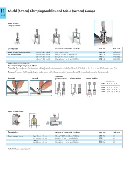
Shield (screen)
clamping saddles
Description Diameter of Connectable Conductor Item No. Pack. Unit
Shield (screen) clamping saddle, 11 mm/0.433 in wide up to 8 mm/0.315 in 790-108 50 (5x10)
incl. knurled screw 19 mm/0.748 in wide 7 mm/0.276 in to 16 mm/0.63 in 790-116 50 (5x10)
27 mm/1.063 in wide 6 mm/0.236 in to 24 m /0.944 in 790-124 50 (5x10)
43 mm/1.693 in wide 22 mm/0.866 in to 40 mm/1.575 in 790-140 50 (5x10)
Note: Not for ground connections!
Recommended tightening torque: 0.5 Nm
Assembly: The shield (screen) clamping saddle is shipped ready for direct connection to the busbar 10 mm (0.394 in) x 3 mm (0.118 in) or to a drilled mounting plate. After
connection, tighten the knurled screw to complete the installation.
Removal: To remove a shield (screen) clamping saddle, unscrew until ratcheted mechanism is released, then slightly tip saddle and remove the clamping saddle.
Installation
Assembly Removal position delivery Closed position Removal position
Dimensions in mm D E F
<_____________A_____________> <__________F __________> <______________E______________> 790-108 51 15 8 16 55 42
Item No.
A
B
C
53 15 16 16 57 45
790-116
790-124
78 15 24 16 83 58
(_10_) (_C_) (_10,1_) 790-140 97 15 40 16 100 73
<__B__> (_C+3 _) <__17__> <__D__>
Shield (screen) clamps <________25________>
<_____________ Hmax . _____________> 3 <
<____B____> >
Description Diameter of Connectable Conductor Item No. Pack. Unit
Shield (screen) camps H max 40 mm, B 10 mm 1.5 mm/0.059 in to 6.5 mm/0.256 in 791-107 50
H max 47 mm, B 17 mm 5 mm/0.197 in to 11 mm/0.434 in 791-111 50
H max 63 mm, B 23 mm 10 mm/0.394 in to 17 mm/0.670 in 791-117 50
H max 78 mm, B 30 mm 16 mm/0.631 in to 24 mm/0.946 in 791-124 50
Note: Not for ground connections!