
Page 659 - Wago_AutomationTechnology_Volume3_2015_US.pdf
P. 659
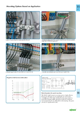
Mounting Options Based on Application                                                                   11

                                                                                                                    657


         – carrier with grounding foot, busbar parallel to the rail  – isolated mounting carriers for a common shield (screen) reference potential,
                                                               independent of the housing potential


         – U-shaped copper busbar 10 mm (0.394 in) x 3 mm (0.118 in)  – snap into any metal plate up to max. thickness 3 mm/0.118 in


           Negative shield (screen) attenuation                Shield (screen)
                                                                                             4
                                                               clamping saddle size  <_   _>    >    <
                                                                                  X
                   dB                                          Distance   X                                    max. 3  <_____
                   0                                           11 mm     9.5 mm
                   - 10                                                                  14
                                                               Distance   Y             <__   __>    2     <
                   - 20                                        19 mm     17.5 mm                     >          >
                                                               27 mm     25.5 mm
                   - 30
                                                               43 mm     41.5 mm  <________   ________>
                                                                                      Y
                   - 40
                   - 50
                   - 60
                      Admissible limiting value                Hole dimensions for panel mounting                  11
                   - 70
                                                               The WAGO shield (screen) connecting system is highly effective
                   - 80
                                                               because the clamping unit can be brought very close to the
                   - 90
                                                               unshielded part of the cable. Additionally, the spring material is
                   -100
                     0.01   0.1     1      10    100           part of the clamping saddle, giving good electrical connection
                                                 MHz
                                                               and compensating for any deformation in the braiding. The system
                                                               also acts as a partial strain relief.