
Page 654 - Wago_AutomationTechnology_Volume3_2015_US.pdf
P. 654
11 WAGO DALI Multi-Sensor Kit
652
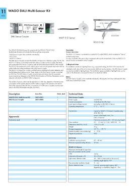
DALI Sensor Coupler
MULTI 3 CI Sensor
ECO CI Kit
The WAGO DALI Multi-Sensor Kit is paired with the WAGO 753-647 DALI Assembly
Multi-Master Module and includes the following three components: Sensor connection
- DALI Sensor Coupler (also available individually) The MULTI 3 CI Sensor is connected to a 4-pole RJ-10 socket (4P4C), which is marked as “Sensor”
- ECO CI Kit on the housing cover.
- MULTI 3 CI Sensor For easy connection, the sensor plug is equipped with a quick-connect latch. Only one MULTI 3 CI
The DALI Sensor Coupler connects the MULTI 3 CI Sensor to a DALI bus system. For this, the Sensor must be connected to sensor coupler.
MULTI 3 CI Sensor is connected to the DALI Sensor Coupler via RJ-10 socket. DALI termi-
nals connect the DALI Sensor Coupler to both the DALI network and WAGO DALI Module. Ceiling installation
The ECO CI Kit contains two covers, which can be used as touch guards and strain relief for For installation outside of a lighting fixture (e.g., suspended ceiling), the ECO CI Kit must also be
cables within the ceiling installation of the DALI Sensor Coupler. attached to both sides of the unit to ensure strain relief and touch protection. The DALI Sensor Coupler
The MULTI 3 CI Sensor has a motion and light sensor, enabling both motion detection and
can also be installed in lighting fixtures. The installation spaces available in lighting fixtures can be
daylight-dependent lighting control. Power supply to the DALI Sensor Coupler is provided used, as the dimensions correspond to those of an electronic ballast.
via DALI line. The DALI Sensor Coupler transmits measured values from the connected
sensor channels as telegrams to the WAGO DALI Module via DALI line. Parameters can be
Note:
adjusted individually via WAGO DALI Configurator.
The DALI Sensor Coupler is also available individually, allowing the unit to be combined with other
multi-sensor models from Osram.
The number of sensors, which can be operated on a DALI line, depends on the total power
consumption of the specific devices and the address range for the actuators and sensors.
Due to the capacity of the DALI bus, a maximum of 16 DALI sensor couplers must be oper-
ated on the DALI Multi-Master Module (753-647).
Description Item No. Pack. Unit Technical Data
WAGO DALI Multi-Sensor Kit 2851-8201 1 DALI Sensor Coupler
DALI Sensor Coupler 2851-8202 1 Power supply via DALI line
Current consumption 5 mA (from the DALI line)
Input signal voltage/current: according to MULTI 3 CI Sensor
Operating temperature 0 °C ... +50 °C
Connections Inputs: for MULTI 3 CI Sensor’s modular plug
4P4C (RJ-10),
sensor cable length, max. 5 m
Approvals
DALI connection:
Conformity mark 1 Push-wire connectors, 8.5 – 9.5 mm strip length
Cross sections 0.5 – 1.5 mm² (s + f-st) / AWG 20 – 16
Dimensions (mm) W x H x D 118 x 21 x 30
Weight 35 g
Storage temperature -25 °C ... +70 °C
Relative humidity (non-condensing) 5 – 93 %
Degree of protection IP20
ECO CI Kit
Installation opening diameter 42 – 48 mm
Minimum suspended ceiling distance 25 mm
MULTI 3 CI Sensor
Maximum total length of signal line
(incl. all connections to the control
units) 100 m
Dimensions (Diameter x H) 50 x 25 mm
Light sensor detection area 20 – 600 lx (measured on the sensor),
opening angle approx. 90°
Recommended installation height 2 – 4 m
Motion detection area Conical, opening angle approx. 80°,
depending on installation height 4 – 8 m