
Page 2 - Exlar - Hazardous location SLM/SLG class 1 division 2
P. 2
Hazardous Location SLM/SLG Class I Division 2
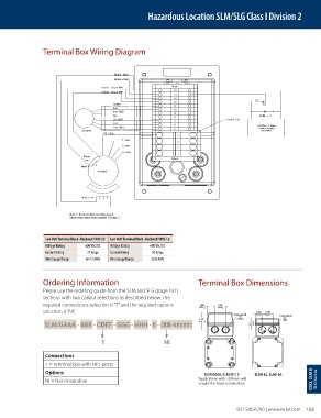
Terminal Box Wiring Diagram
Brake - Blue
Brake + Red
Therm - Org or Wht Blank
15
Therm - Org or Wht
14
13
12
Shield 11
Exc 10
Exc GND 9 • ________ •
I
________ I
I
I I
Sin 8 ____ ____ ____
Sin GND 7 Barrier End
Cos 6 + -
Cos GND 5 24 Vdc ~ 1 amp
Power Supply
Resolver for brake
PE - Grn
4
T - Blu
3
S - Blk
2
R - Red
1
Therm
Sw. Blank
Note 1
Actuator
Brake Coil
Note 1: Thermal switch normally closed;
opens when stator temp exceeds 130 deg. C.
Low Volt Terminal Block–Rockwell 1492-L3 Low Volt Terminal Block–Rockwell 1492-L6
Voltage Rating 600 VAC/DC Voltage Rating 600 VAC/DC
Current Rating 27 Amps Current Rating 50 Amps
Wire Gauge Range 26-12 AWG Wire Gauge Range 20-8 AWG
Ordering Information Terminal Box Dimensions
Please use the ordering guide from the SLM and SLG (page 161)
sections with two callout selections as described below. The
required connections selection is “T” and the required options 1.034 1.375
26.3 34.9
selection is “NI”. 1.260 1.970
Power and I/O 32.0 50.0
2X Power and I/O
2X
2.232 1/2 NPT 1 NPT
SLM/GAAA - BBB - CDEF - GGG - HHH - II - (XX-#####) 56.7 2.170
55.1
T NI
Connections
T = Terminal box with NPT ports
Options SLM/G090, SLM/G115 * SLM142, SLM180
* Applications with >20A rms will
NI = Non-Incendive CID2, SLM & SLG Seri es
require the larger terminal box.
952.500.6200 | www.exlar.com 155