
Page 4 - Exlar - Hazardous location SLM/SLG class 1 division 2
P. 4
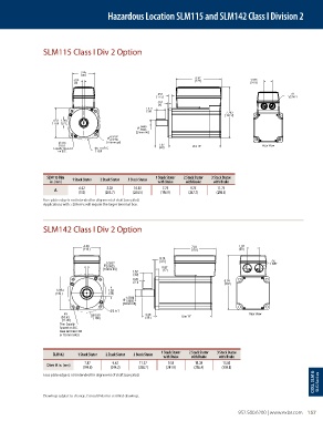
Hazardous Location SLM115 and SLM142 Class I Division 2


                 SLM115 Class I Div 2 Option


                               3.45
                                88
                                                                          6.97
                            .315                                          177                 1.375
                             8                                                                 34.9
                                                            .453                                              2X
                                                            11.5                                            1/2 NPT
                                                            .157
                                                            4
                                                        1.417
                                                        36
                                                                                     7.763
                                                                                     197.2
                     4.53  1.06
                     115  27
                                                     .9449
                                                     .9445
                                                    [24mm h6]
                                          4.3297
                                          4.3289
                        .335             [110mm g6]
                        8.5                                 1.97         Dim "A"                   Rear View
                     Equally Spaced  5.118 B.C.              50
                       on B.C.       130
                   SLM115 Dim  1 Stack Stator  2 Stack Stator  3 Stack Stator  1 Stack Stator  2 Stack Stator  3 Stack Stator
                     in. (mm)                               with Brake  with Brake  with Brake
                               6.02      8.02      10.02      7.75      9.75      11.75
                     A
                              (153)     (203.7)    (254.5)   (196.9)   (247.7)    (298.5)
                 Face plate edge is not intended for alignment of shaft (use pilot)
                 Applications with >20A rms will require the larger terminal box.


                 SLM142 Class I Div 2 Option


                                4.49                                     7.01             1.97
                                114                                      178               50
                                                             0.14
                                                             3.5                                      2X
                                         0.3937                                                       1 NPT
                                        Ø 0.3923              0.67
                                        [10mm h9]             17
                                                   1.57
                                                   40
                                                   0.20
                                                   5.1                               9.14
                                                                                     232
                      5.59               1.38
                      142                 35
                                                1.2598
                                               Ø 1.2592
                                               [32mm h6]
                                          Ø 5.117
                         4X        Ø 6.50              2.28                                   Rear View
                        Ø 0.43      165                 58           Dim "A"
                        11.00
                       Thru Equally
                       Spaced on B.C.
                       Case will Clear 3/8
                       or 10 mm SHCS
                                                             1 Stack Stator  2 Stack Stator  3 Stack Stator
                     SLM142   1 Stack Stator  2 Stack Stator  3 Stack Stator
                                                              with Brake  with Brake  with Brake
                                 7.87      9.62      11.37      9.53      11.28     13.03
                  Dim A in. (mm)
                                (199.8)   (244.2)    (288.7)   (241.9)   (286.4)    (330.8)
                                                                                                                      CID2, SLM &   SLG Seri es
                 Face plate edge is not intended for alignment of shaft (use pilot)
                 Drawings subject to change. Consult Exlar for certified drawings.

                                                                                           952.500.6200 | www.exlar.com    157