
Page 5 - Parker - Instrumentation process analyzer condensed catalog
P. 5
IR4000 Series continued
Ordering Information
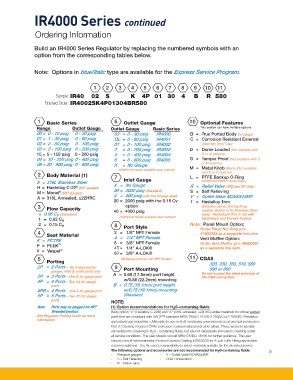
Build an IR4000 Series Regulator by replacing the numbered symbols with an
option from the corresponding tables below.
Note: Options in blue/Italic type are available for the Express Service Program.
1 2 3 4 5 6 7 8 9 10 11
Sample: IR40 02 S K 4P 01 30 4 B R 580
Finished Order: IR4002SK4P01304BR580
1
Basic Series 6 Outlet Gauge 10 Optional Features
Range Outlet Gauge Outlet Gauge Basic Series This section can have multiple options
00 = 0 - 10 psig 0 - 30 psig 03 = 0 - 30 psig IR4000 B = True Ported Body (no plugs)
01 = 1 - 30 psig 0 - 60 psig OL = 0 - 60 psig IR4001 C = Corrosion Resistant External
02 = 2 - 60 psig 0 - 100 psig 01 = 0 - 100 psig IR4002 (Stainless Steel Cap)
03 = 3 - 100 psig 0 - 200 psig 2 = 0 - 200 psig IR4003 D = Dome Loaded (Not available with
15 = 5 - 150 psig 0 - 200 psig 4 = 0 - 400 psig IR4004 G or M options)
04 = 10 - 250 psig 0 - 400 psig 6 = 0 - 600 psig IR4005 G = Tamper Proof (Not available with D
05 = 20 - 500 psig 0 - 600 psig X = No Gauge or M options)
(Additional ranges available upon request) M = Metal Knob (Black) (Not available
with D or G options)
2 Body Material (1) L = PTFE Backup O-Ring
7 Inlet Gauge
S = 316L Stainless Steel X = No Gauge (PCTFE and PEEK™ Seats Only)
®
H = Hastelloy C-22 (SST gauges) R = Relief Valve (4PB and 5P Only)
®
M = Monel (SST gauges) 30 = 3000 psig (Standard) S = Self Relieving
A = 316L Annealed, ≤22HRC 4 = 400 psig with the 10 psig range V = Outlet Valve NOVAS44MF
20 = 2000 psig with the 0.15 Cv T = Hastelloy Trim
option
3
Flow Capacity 40 = 4000 psig (Includes carrier and back-up
washer. Option is for Stainless Steel
= 0.06 C (Standard) (Additional ranges available upon request) body - Hastelloy® Trim is std with
v
1 = 0.02 C v Hastelloy® and Monel® bodies)
2 = 0.15 C v 8 Port Style Note: Panel Mount Option:
Order Panel Nut Ring p/n:
4
Seat Material 2 = 1/8” NPT Female 41900363 as a separate line item.
4 = 1/4” NPT Female
K = PCTFE 6 = 3/8” NPT Female Vent Muffler Option:
P = PEEK ™ 4T = 1/4” A-LOK® Order Vent Muffler p/n: 46600581
as a separate line item.
V = Vespel ®
6T = 3/8” A-LOK®
5 (All Gauge ports are 1/4” NPT Female) 11 CGA#
Porting 320, 330, 350, 510, 580
2P = 2 Ports - No X required for 9 Port Mounting 590 or 660
gauges, Inlet & outlet ports only Do not exceed the rated pressure of
3P = 3 Ports - One X for gauge port A = 0.69 (17.5mm) port height the CGA connection.
4P = 4 Ports - Two X’s for gauge w/0.88 (22.2mm) mounting
ports B = 0.75 (19.1mm) port height
4PB = 4 Ports - One X for gauge port w/0.75 (19.1mm) mounting
5P = 5 Ports - Two X’s for gauge (Standard)
ports NOTE:
Note: Ports may be plugged for NPT (1) Option recommendations for H S-containing fluids
2
threaded product. Body option “H” (Hastelloy C-22®) and “A” (316L annealed, ≤22HRC) utilize materials for critical wetted
See Regulator Porting Guide for more parts that are compliant with NACE™ standard MR0175/ISO 15156-3:2003/Cor.2:2005(E), Petroleum
information. and natural gas industries – Materials for use in H S-containing environments in oil and gas production,
2
Part 3: Cracking-resistant CRAs (corrosion-resistant alloys) and other alloys. These wetted materials
are resistant to cracking in H S - containing fluids, but are not necessarily immune to cracking under
2
all service conditions. The user should consult MR0175/ISO 15156 for further guidance. The user
should consult Instrumentation Product Division Catalog 4230/4233 for A-Lok Tube Fitting application
recommendations. It is the user’s responsibility to select materials suitable for the intended service.
The following options and accessories are not recommended for H S-containing fluids: 5
2
- Pressure gauges - V – Outlet Valve NOVAS44MF
- S – Self Relieving - CGA connections
- R - Relief valve