
Page 7 - Parker - Instrumentation process analyzer condensed catalog
P. 7
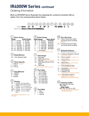
IR4000W Series continued


               Ordering Information


               Build an IR4000W Series Regulator by replacing the numbered symbols with an
               option from the corresponding tables below.


                                        1    2     3    4    5     6    7    8     9    10    11   12
                         Sample:  IR40  01  W           K  3P  X            FS MMM  A         L
                    Finished Order:  IR4001WK3PXFSMMMAL


                                                 6
                 1
                     Basic Series                    Outlet Gauge                 10  Port Mounting
                 Range         Outlet Gauge     Outlet Gauge     Basic Series    A  =  0.69 (17.5mm) port height
                   00 =  0 - 10 psig   0 - 30 psig  03  =  0 - 30 psig   IR4000W     w/0.88 (22.2mm) mounting
                 01 =  1 - 30 psig   0 - 60 psig  OL  =  0 - 60 psig   IR4001W      (Standard)
                 02 =  2 - 60 psig   0 - 100 psig  01  =  0 - 100 psig   IR4002W  B  =  0.75 (19.1mm) port height
                 03 =  3 - 100 psig  0 - 200 psig  2    =  0 - 200 psig   IR4003W    w/0.75 (19.1mm) mounting
                 15 =  5 - 150 psig  0 - 200 psig  4    =  0 - 400 psig   IR4004W
                 04 = 10 - 250 psig  0 - 400 psig  6    =  0 - 600 psig   IR4005W
                 05 = 20 - 500 psig  0 - 600 psig  X    =  No Gauge                11  Optional Features
                                                    (Additional ranges available upon request)     This section can have multiple options
                 2   Body Material                 7    Inlet Gauge              C  =  Corrosion Resistant External
                                                                                      (Stainless Steel Cap)
                 W =  316L Stainless Steel       X  =  No Gauge                  D  =  Dome Loaded (Not available with
                                                                                      G or M options)
                                                 30 =  3000 psig (Standard)      G  =  Tamper Proof (Not available with D
                 3
                                                                                      or M options)
                     Flow Capacity               4  =  400 psig with the 10 psig range  M  =  Metal Knob (Black) (Not available
                                                 20 =  2000 psig with the 0.15 Cv

                  =  0.06 Cv (Standard)               option                          with D or G options)
                1 =  0.02 C v                    40 =  4000 psig                 L  =   PTFE Backup O-Ring
                2 =  0.15 C v                      (Additional ranges available upon request)  (PCTFE and PEEK™ Seats Only)
                                                                                 R  =  Relief Valve (4PB and 5P Only)
                                                   8  Port Style                 S  =  Self Relieving
                 4
                     Seat Material              4T  =  1/4” A-LOK®               T  =  Hastelloy Trim
                 K  =  PCTFE                    6T  =  3/8” A-LOK®                     (Includes carrier and back-up washer.)
                 P  =  PEEK ™                   8T  =  1/2” A-LOK®               Note:  Panel Mount Option:
                 V  = Vespel ®                  FS  =  1/4” Face Seal                Order Panel Nut Ring p/n:
                                                FS8 =  1/2” Face Seal                41900363 as a separate line item.
                                                TS  =  1/4” Tube Stub
                 5
                     Porting                    TS6 =  3/8” Tube Stub           12
                 2P  =  2 Ports - No X required for   TS8 =  1/2” Tube Stub          Industrial CGA#
                       gauges, Inlet & outlet ports only                            320, 330, 350, 510, 580
                 3P  =  3 Ports - One X for gauge port                              590 or 660
                                                                                     DISS CGA#
                 4P  =  4 Ports - Two X’s for gauge ports                             634, 716, 718, 724, or 728
                 4PB =  4 Ports - One X for gauge port     9  Port Style               Do not exceed the rated pressure of
                 5P  =  5 Ports - Two X’s for gauge   M  =  Male                      the CGA connection.
                       ports
                                                 F    =  Female
                 See Regulator Porting Guide for  more   I    =  Internal
                 information


                                                                                                                 7