
Page 10 - Parker - L90LS Mobile directional control valve
P. 10
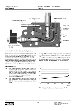
Catalogue HY17-8504/UK                             Mobile Directional Control Valve
        Inlet Section                                      L90LS


                                              Tank connection T1 [25]               Pump connection P1 [26]
                    Pressure relief valve PS [16]


                                                                                                  Gauge port::
                                                                                                  Copied load
                                                                                                  signal LS


                                                                                                  Pump pressure
                                                                                                  PX


                                                                                                  Load signal PL


              Pump unloading function
              BEN [22]


        Inlet section CFC alt. LS1 with pump unloading function.
        The inlet section is available in several basic variants; one for fixed   are plugged. The variant for fixed pumps can be converted easily
        pumps, four for systems with variable pumps and  a simple plate   in the field to work with variable pumps, and vice versa. (CFC ↔
        for use when none of the inlet section’s integrated functions   LS1).
        is required. Inlet sections are equipped with pump and tank   Functions for maximum pressure relief, copying of the load
        connections, a connection for the load signal to variable pumps   signal and pump unloading (which blocks the hydraulic energy
        and gauge ports for measuring the pump and load-signal pres-  supply to the valve) can be integrated into the inlet section.
        sures. In all basic variants, the pump connection P1 [26] and
        tank connection T1 [25] are open, while the other connections

        Inlet sections [15]                                  ∆p (bar)
        CFC    Inlet section for systems with fixed pump. The section
               is equipped with an adjustable, pilot-operated pressure
               relief valve, PS [16], which protects the pump and inlet   30
               side of the valve. A built-in bypass regulates excess oil
               directly to tank. The bypass pressure level is controlled
               by the load signal, and is approx. 10 bar above the   20
               actual load-signal pressure.
        LS1    Inlet section for systems with variable pump. Equipped   10
               with an adjustable, pilot-operated pressure relief valve,
               PS [16], which protects the pump and inlet side of the
               valve.                                         0
                                                               0         50        100        150        200
                                                                                                      q (l/min)

                                                            CFC – Idling (no load) pressure drop over bypass. P1 –T1.


                                                          10                        Parker Hannifin
                                                                                    Mobile Controls Division Europe
                                                                                    Borås, Sweden