
Page 9 - Parker - L90LS Mobile directional control valve
P. 9
Catalogue HY17-8504/UK Mobile Directional Control Valve
Hydraulic circuits L90LS
50 66 76 75 50
PS
B A B A TPB
25 T1 40
22 32
P2B
39
20 37
33
15, 16
T3 34
26 P1
PL PX LSPB
LS
67 60 47 60 31
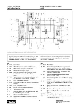
Hydraulic circuit diagram showing basic functions of L90LS.
The item numbers in the hydraulic circuit diagram and table equipped according to the description below. For other equip-
below refer to the valve function areas for which different ment alternatives, see under respective valve-function area
options are available. The valve in the example above is [Item number] in catalogue.
Item Item
No. Code Description No. Code Description
15 CFC Inlet with bypass for systems with fixed pump. 47 TTT Section 1 equipped with pressure compensator,
separate feed reducers for A- and B-ports, and
16 PS Pilot-operated main pressure relief valve.
prepared for port relief valves in both service ports.
20 KB Prepared for load-signal copying. 000 Section 2 without pressure compensator, feed
22 BEN Electrically activated pump-unloading function reducer or port relief valve.
that blocks the pump and unloads the load 50 EC Section 1 equipped with proportional electro-
signal.
hydraulic remote control.
25 T1X Tank connection in the inlet open for by-pass flow CH Section 2 equipped for direct operation with spring
and tank gallery to spool section 1 plugged.
centring.
26 P1 Pump connection in inlet open.
60 D Sections 1 and 2 equipped with spool for double-
31 LSPB Load-signal connection for parallel-connected valve acting function, with service ports blocked in neutral
plugged. position.
32 P2B Pump connection plugged. 66 K Pressure compensator with built-in check valve
function.
33 MF Counter pressure valve with fixed setting.
67 0.8 Restriction of load signal to pressure compensator.
34 T3 Tank connection open.
75 Pressure setting for feed reducers in A- and
37 R Pressure reducing valve with separate safety valve B-ports.
for internal pilot pressure supply.
76A N2 Anti-cavitation valve in A-port.
39 S Internal coarse filter for pilot circuit.
76B Pressure setting for combined port-relief and anti-
40 TPB Prepared for separate tank connection from pilot cavitation valve in B-port.
circuit.
9 Parker Hannifin
Mobile Controls Division Europe
Borås, Sweden