
Page 16 - Parker - L90LS Mobile directional control valve
P. 16
Catalogue HY17-8504/UK Mobile Directional Control Valve
Inlet Section L90LS
Load signal system [20]
The load-signal system consists of a series of shuttle valves, one
for each spool section in the directional valve. The shuttle valves
compare the load signals from all actuated spool sections and
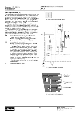
transmit the signal with the highest value to the PL connection in KB - Inlet section without copy spool.
the inlet section. If the valve has a load-signal copying function,
the signal is transmitted to a copy spool, which makes a copy of
the signal and transmits it to the LS port.
If the load-signal chain is extended to a parallel-connected
valve via the LSP port [31], then the highest load signal from the
parallel-connected valve is included in the comparisons made by
the load-signal chain in the first valve.
In the case of the CFC variant of the L90LS, i.e. the variant
fed by a fixed pump, the highest load signal is transmitted to B A
the bypass valve, which regulates the pressure in the pressure
gallery to approx. 10 bar above the value of the signal.
T1B
KB Inlet section machined for copy spool but blocked.
Provides option to install copy spool later.
The load signal goes directly to the bypass in CFC
systems , or to the PL connection in LS systems.
KS Inlet section with copy spool.
The load signal acts on a copy spool, which sends a
copied load signal to the LS connection.
The copying system permits a certain consumption
in the load-signal line to the pump regulator, without
the load signal being influenced. This enables simpler
system construction, with the possibility of installing
logic systems in the LS circuit. Thanks to drainage in
the pump LS regulator, the system gives better winter
operating characteristics with faster response, since
the oil in the LS circuit is always warm. Moreover, it
prevents the tendency for the load to sink slightly at the
beginning of the lifting phase. P1
Inlet sections of type LS2 [15] are normally equipped
with copy spools.
PL PX
/ Not machined for copy spool.
LS
KS - Inlet section with copy spool.
Copied load
signal LS
Pump pressure
PX
Load signal PL
KS - Inlet section with copy spool.
16 Parker Hannifin
Mobile Controls Division Europe
Borås, Sweden