
Page 9 - Apollo - Water Pressure Reducing Valves
P. 9
WATER PRESSURE REDUCING VALVES
Compact Design for Residential & Light Commercial Applications
PRC SERIES (36C) MATERIALS
Item Description Item Description
1 1 Adjusting Bolt (Stainless Steel) 16 O’Ring (FDA Nitrile)
2 2 Nut (Stainless Steel) 17 O’Ring (FDA Nitrile)
3 24 3 Tee Nut (Zinc Plated Steel) 18 Lock Nut (300 Series SS)
4
25 4 Cap (G.F. Celcon) 19 Seat Ring (300 Series SS)
7 26 5 Hex Bolt (300 Series SS) 20 Seat Disc (FDA EPDM)
8 6 Pressure Plate (Brass) 21 Disc Holder (Brass)
5 7 Diaphragm (FDA EPDM W/Polyester) 22 Clean-Out Plug (Brass)
10 6
27 9 8 Friction Ring (Brass) 23 Body, Machined (Cast Bronze)
28 23 9 Cartridge Ret. Washer (Brass) 24 Spring Disc (Zinc Plated Steel)
29 11 10 Stem (Brass) 25 Nameplate (Aluminum)
11 O’Ring (FDA Nitrile) 26 Spring (Zinc Plated Music Wire)
12
14 12 O’Ring (FDA Nitrile) 27 Union Nut (Brass)
13 15 13 Cartridge Housing (G.F. Noryl) 28 Union Washer (FDA Nitrile)
16 14 Screen (300 Series SS) 29 Union Tail Piece (Brass)
17 20 15 O’Ring (FDA Nitrile)
18 22 21
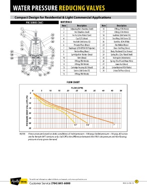
FLOW CHART
NOTE: Flow curves are based on static conditions of: Inlet pressure = 100 psig: Outlet pressure = 50 psig. All curves
are for female NPT versions only. Fall Off is the difference between the PRV’s set pressure and the flowing
pressure at any given demand.
For additional information, submittal sheets and manuals, visit www.apollovalves.com
Customer Service (704) 841-6000 REV. 6-18-15 9