
Page 202 - Wago_PCB_TerminalBlocksConnectors_Volume2_2015_US
P. 202
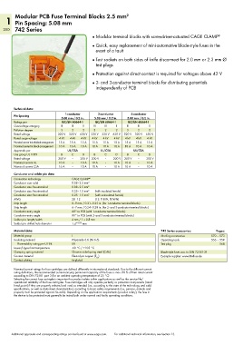
Modular PCB Fuse Terminal Blocks 2.5 mm                2
    1 Pin Spacing: 5.08 mm
   200 742 Series
                                              ●  Modular terminal blocks with screwdriver-actuated CAGE CLAMP ®

                                              ●  Quick, easy replacement of mini-automotive blade-style fuses in the
                                                event of a fault

                                              ●  Test sockets on both sides of knife disconnect for 2.0 mm or 2.3 mm Ø
                                                test plugs
                                              ●  Protection against direct contact is required for voltages above 42 V

                                              ●  2- and 3-conductor terminal blocks for distributing potentials
                                                independently of PCB


        Technical data:

        Pin Spacing              1-conductor     2-conductor     3-conductor
                               5.08 mm / 0.2 in.  5.08 mm / 0.2 in.  5.08 mm / 0.2 in.
        Ratings per            IEC/EN 60664-1   IEC/EN 60664-1  IEC/EN 60664-1
        Overvoltage category   III  III   II   III  III   II   III  III   II
        Pollution degree       3    2     2    3    2     2    3     2    2
        Rated voltage        320 V  320 V  630 V  320 V  320 V  630 V  320 V  320 V  630 V
        Rated surge voltage   4 kV  4 kV  4 kV  4 kV  4 kV  4 kV  4 kV  4 kV  4 kV
        Nominal current in individual arrangement  15 A  15 A  15 A  15 A  15 A  15 A  15 A  15 A  15 A
        Nominal current in block arrangement  10 A  10 A  10 A  10 A  10 A  10 A  10 A  10 A  10 A
        Approvals per             UL/CSA          UL/CSA          UL/CSA
        Use group UL 1059      B    C     D    B    C     D    B    C     D
        Rated voltage         300 V  –   300 V  300 V  –   300 V  300 V  –   300 V
        Nominal current UL    10 A  –    10 A  10 A  –   10 A  10 A  –   10 A
        Nominal current CSA   16 A  –    10 A  10 A  –   10 A  10 A  –   10 A
        Conductor and solder pin data:
        Connection technology       CAGE CLAMP ®
        Conductor size: solid       0.08–2.5 mm 2
        Conductor size: fine-stranded  0.08–2.5 mm 2
        Conductor size: fine-stranded  0.25–1.5 mm 2  (with insulated ferrule)
        Conductor size: fine-stranded  0.25–1.5 mm 2  (with uninsulated ferrule)
        AWG                         28–12       (12: THHN, THWN)
        Strip length                8–9 mm / 0.31–0.35 in. (for 1-conductor terminal blocks)
        Strip length                6–7 mm / 0.24–0.28 in. (for 2- and 3-conductor terminal blocks)
        Conductor entry angle       60° to PCB (with 1-conductor terminal blocks)
        Conductor entry angle       90° to PCB (with 2- and 3-conductor terminal blocks)
        Solder pin: length/width    4 mm / 1 x 0.8 mm
        Solder pin: drilled hole diameter  1.4 + 0.05  mm
        Material data:                                                          742 Series accessories:    Pages:
        Material group              I                                           Marking accessories     570 – 573
        Insulating material         Polyamide 6.6 (PA 6.6)                      Operating tools         556 – 559
          Flammability rating per UL 94  0V                                     Test plug                    568
        Lower/Upper limit temperature  -60 °C / +105 °C
        Clamping spring material    Chrome nickel spring steel (CrNi)           Blade-style fuses acc. to DIN 72581-3f
        Contact material            Electrolytic copper (E )                    Example supplier: www.littelfuse.de
                                                Cu
        Contact plating             tin-plated
        Nominal current ratings for fuse cartridges are defined differently in international standards. Due to the different current
        rating definitions, the recommended current-carrying permanent capacity of the fuses is max. 80 % of their rated current
        according to DIN 72581 part 3 (for an ambient operating temperature of 23 °C).
        Selecting the correct fuse cartrigde is important for product safety within applications as well as the service life/
        operational reliability of the fuse cartrigdes. Fuse cartridges will only operate perfectly as protection components (rated
        break point) if they are properly selected and used as intended (i.e., according to the state of the technology and valid
        specifications, as well as data sheet characteristics), according to basic safety requirements (i.e., persons, animals and
        property must be protected against hazards). Depending on the application requirements (product safety), the fuse in
        the device to be protected must generally be tested both under normal and faulty operating conditions.


       Additional approvals and corresponding ratings can be found at www.wago.com.   For additional technical information, see Section 13.