
Page 204 - Wago_PCB_TerminalBlocksConnectors_Volume2_2015_US
P. 204
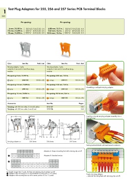
1   Test Plug Adapters for 255, 256 and 257 Series PCB Terminal Blocks


   202


                    Pin spacing:                       Pin spacing:

          5 mm / 0.197 in.    320 V/2.5 kV/2 (II)  6 A   5.08 mm / 0.2 in.    320 V/2.5 kV/2 (II)  6 A
        7.5 mm / 0.295 in.    630 V/   4 kV/2 (II)  6 A   7.62 mm / 0.3 in.   630 V/   4 kV/2 (II)  6 A
         10 mm / 0.394 in.  1000 V/   6 kV/2 (II)  6 A  10.16 mm / 0.4 in. 1000 V/   6 kV/2 (II)  6 A


        Color        Item No.     Pack. Unit  Color     Item No.     Pack. Unit
        Test plug adapter, 1-pole,         Test plug adapter, 1-pole,
        socket for 2 mm and 2.3 mm Ø test plugs,    socket for 2 mm and 2.3 mm Ø test plugs,
        modular                            modular

        Pin spacing: 5 mm / 0.197 in.      Pin spacing: 5.08 mm / 0.2 in.
          gray       249-110     100 (4 x 25)  orange   249-111     100 (4 x 25)
        Pin spacing: 7.5 mm / 0.295 in.    Pin spacing: 7.62 mm / 0.3 in.
                                                                              Assembling a multipole test plug adapter.
          gray       249-112     100 (4 x 25)  orange   249-113     100 (4 x 25)
        Pin spacing: 10 mm / 0.394 in.     Pin spacing: 10.16 mm / 0.4 in.

          gray       249-114     100 (4 x 25)  orange   249-115     100 (4 x 25)

        Accessories                        Item No.                     Pages:
        Test plug, with 500 mm cable, 2.3 mm Ø, yellow   210-137         568
        Test plug, with 500 mm cable, 2 mm Ø, red  210-136               568


           <____19,5____>  Interfaces                                         Inserting a 6-pole test plug adapter assembly into a
                                                                              terminal strip.
         <_____21 ,5_____>  1 <    <_13,2_><___17 ,3 ___>  5,2  2< <  ___16,9 ___>  <  6,8  <  6,6  <9,9>


         0,2  __>  <__14,5 __>  >    >  >             <_13 __><  _  >  >  __13,6 __ >  <
                                    2,6
                       > 4,3 <      __> <___15___><__12 __>
                      >  6,5 <__14 __>                    <__ 14,2 __> <___16,8___>
        Test plug adapter on:   255 Series   256 Series        257 Series
                                                                              Testing terminal blocks with terminated conductors.


                                        Adapters A: Snap-in mounting foot with retaining clip cut off

        1   A  A  B  B  B  B  B  A  A   Adapters B: Standard version


        2
            B  B  B  A  A  A  A  A  A  A  A  A  B  B  B

       For lengths longer than 7 poles, the feet and retaining clip should be cut off!
       1 Adapters with mounting foot cut off assembled on both ends (7 to 9 poles)  9-pole test plug adapter,
       2 Adapters with mounting foot cut off in center position (10 to 15 poles)  — external mounting feet with retaining clip cut off.