
Page 280 - Wago_PCB_TerminalBlocksConnectors_Volume2_2015_US
P. 280
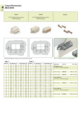
Cutout Dimensions
   4 MCS MINI
   278


                      Cutout                             Cutout                             Screws

             for 734 Series male connectors    for 2734 Series female connectors
                  with fixing flanges                with fixing flanges


                                  <                                  <

              _>   <_  L1 ±0,1     >                  <__       __>  >
                                                  _>   <_
           5,9 ±0,1            Ø   13,9 ±0,1   5,9 ±0,1           Ø   14 ±0,1
                                                           ±0,1
                                                          L1
                 <__       __>
                                                          L2
                                                           ±0,1
                <____       ____>                   <____       ____>
                        ±0,1
                      L2
       Drilled hole Ø: Depends on the type of screw used (see fixing screws).  M 2.5 x 10 screws with nuts (e.g., for fixing flanges)
        Table 1:                           Table 2:
       Pole No.  Pin Spacing: 3.5   Pin Spacing: 3.81  Pole No.  Pin Spacing: 3.5   Pin Spacing: 3.81  Dimensions  Item No.   Pack. Unit
                L1     L2     L1      L2           L1     L2      L1     L2
          2     9.8    15.5   10.1   16.1    2     10.4   15.5   11.0   16.1  Self-tapping screws
          3    13.3    19.0   13.9   19.9    3     13.9   19.0   14.8   19.9  for 1.8 mm  ± 0.1  mm Ø mounting hole
          4    16.8    22.5   17.7   23.7    4     17.4   22.5   18.6   23.7
          5    20.3    26.0   21.5   27.6    5     20.9   26.0   22.5   27.6
          6    24.0    29.4   25.6   31.3    6     24.6   29.4   26.5   31.3  B 2.2 x 9.5 mm  209-147  200 ( 2 x 100 )
          7    27.5    32.9   29.4   35.1    7     28.1   32.9   30.3   35.1
          8    31.0    36.4   33.2   38.9    8     31.6   36.4   34.1   38.9  B 2.2 x 13 mm  231-194  200 ( 2 x 100 )
          9    34.5    39.9   37.0   42.7    9     35.1   39.9   37.9   42.7
         10    38.0    43.4   40.8   46.5   10     38.6   43.4   41.7   46.5  Screws with nuts
         11    41.5    46.9   44.6   50.3   11     42.1   46.9   45.5   50.3  for 2.5 mm  ± 0.1  mm Ø mounting hole
         12    45.0    50.4   48.4   54.1   12     45.6   50.4   49.3   54.1
         13    48.8    53.8   52.5   57.8   13     49.4   53.8   53.4   57.8
         14    52.3    57.3   56.3   61.6   14     52.9   57.3   57.2   61.6  M 2 x 12 mm  231-195    200 ( 2 x 100 )
         15    55.8    60.8   60.1   65.5   15     56.4   60.8   61.1   65.5
         16    59.3    64.3   64.0   69.3   16     59.9   64.3   64.9   69.3
         17    62.8    67.8   67.8   73.1   17     63.4   67.8   68.7   73.1
         18    66.3    71.3   71.6   76.9   18     66.9   71.3   72.5   76.9  Screws with nuts
         19    69.9    74.7   75.5   80.6   19     70.5   74.7   76.4   80.6  for 3.0 mm  ± 0.1  mm Ø mounting hole
         20    73.4    78.2   79.3   84.4   20     74.0   78.2   80.2   84.4
         21    76.9    81.7   83.1   88.2   21     77.5   81.7   84.0   88.2
         22    80.4    85.2   86.9   92.0   22     81.0   85.2   87.8   92.0  M 2.5 x 10 mm  231-295  200 ( 2 x 100 )
         23    83.9    88.7   90.7   95.8   23     84.5   88.7   91.6   95.8
         24    87.4    92.2   94.5   99.6   24     88.0   92.2   95.4   99.6