
Page 602 - Wago_PCB_TerminalBlocksConnectors_Volume2_2015_US
P. 602
Tests and Testing Procedures per IEC/EN Standards (continued)
13 Electrical Tests (continued)
600
• Power-Frequency Withstand Voltage Test per IEC/EN 60998-1
This test procedure verifies creepage distances. Creepage distances, i.e., the distances of creeping currents, are caused by con-
ductive impurities on the surface of the insulation housing. Apart from the amount of impurities to which a terminal block, for
example, is subjected, the plastic material and housing design are also involved in generating creeping currents. The insulation
material of the housing may be carbonized by a creeping current, which increases conductivity even more.
The specimen is tested using a power-frequency withstand voltage for a short time. For example, a PCB terminal block designed
to operate at 320 V nominal voltage is usually tested using 2500 V alternating voltage for one minute. The test is considered to
be passed if no flashovers or breakdowns have occurred.
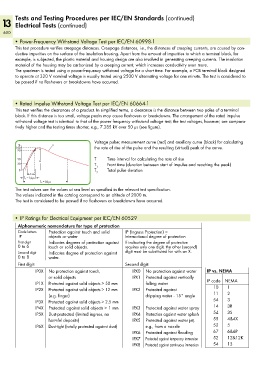
• Rated Impulse Withstand Voltage Test per IEC/EN 60664-1
This test verifies the clearances of a product. In simplified terms, a clearance is the distance between two poles of a terminal
block. If this distance is too small, voltage peaks may cause flashovers or breakdowns. The arrangement of the rated impulse
withstand voltage test is identical to that of the power frequency withstand voltage test; the test voltages, however, are compara-
tively higher and the testing times shorter, e.g., 7.385 kV over 50 µs (see figure).
Voltage pulse; measurement curve (red) and auxiliary curve (black) for calculating
% u
100 the rate of rise of the pulse and the resulting (virtual) peak of the curve.
90
50 û T Time interval for calculating the rate of rise
30 T Front time (duration between start of impulse and reaching the peak)
1
0 T Total pulse duration
(_T _) 2
T 1 = 1,2 µs
<__________ T 2 = 50 µs __________>
The test values are the values at sea level as specified in the relevant test specification.
The values indicated in the catalog correspond to an altitude of 2000 m.
The test is considered to be passed if no flashovers or breakdowns have occurred.
• IP Ratings for Electrical Equipment per IEC/EN 60529
Alphanumeric nomenclature for type of protection
Code letters Protection against touch and solid IP (Ingress Protection) =
IP objects or water International degree of protection
First digit Indicates degrees of protection against If indicating the degree of protection
0 to 6 touch or solid objects. requires only one digit, the other (second)
Second digit Indicates degree of protection against digit must be substituted for with an X.
0 to 8 water.
First digit: Second digit:
IP0X No protection against touch, IPX0 No protection against water IP vs. NEMA
or solid objects IPX1 Protected against vertically
IP1X Protected against solid objects > 50 mm falling water IP code NEMA
IP2X Protected against solid objects > 12 mm IPX2 Protected against 10 1
(e.g. finger) dripping water - 15° angle 11 2
IP3X Protected against solid objects > 2.5 mm 54 3
IP4X Protected against solid objects > 1 mm IPX3 Protected against water spray 14 3R
IP5X Dust-protected (limited ingress, no IPX4 Protection against water splash 54 3S
harmful deposits) IPX5 Protected against water jet, 55 4&4X
IP6X Dust-tight (totally protected against dust) e.g., from a nozzle 52 5
IPX6 Protected against flooding 67 6&6P
IPX7 Protected against temporary immersion 52 12&12K
IPX8 Protected against continuous immersion 54 13