
Page 598 - Wago_PCB_TerminalBlocksConnectors_Volume2_2015_US
P. 598
Tests and Testing Procedures per IEC/EN Standards (continued)
13 Electrical Tests (continued)
596
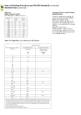
Table A.2: Creepage Distances, Rated Voltages,
Height Correction Factors Material Groups
(DIN EN 60664-1/VDE 0110, Part 1)
Criteria for dimensioning creepage dis-
Height (eleva- Standard Multiplier for tances are the rated voltages, pollution
tion) air pressure distance degrees and material groups.
m kPa The pollution degrees specified for the
2000 80 1 clearances, and its quoted allocation to
3000 70 1.14 locations, is also applicable for creepage
4000 62 1.29
5000 54 1.48 distances.
6000 47 1.7 Tables F.3 a and F.3 b of
7000 41 1.95 DIN EN 60664-1/ VDE 0110, Part 1
8000 35.5 2.25 contain the rated voltages which have to
9000 30.5 2.62 be considered for dimensioning the mini-
10000 26.5 3.02 mum creepage distance.
15000 12 6.67
20000 5.5 14.5
Table F.3a: Single-Phase, 3- or 2-Wire, AC or DC Systems
Voltages for Table F.4
Nominal voltage of the supply sys- For insulation line-to-line 1) For insulation line-to-earth 1)
tem (mains) *
All systems Three-wire systems
mid-point grounded
V V V
12.5 12.5
24
25 25
30 32
42
48
50 ** 50
60 63
30 - 60 63 32
100 ** 100
110 125
120
150 ** 160
200 200
110 - 200 200 100
220 250
110 - 220
120 - 240 250
300 ** 320
220 - 440 500 250
600 ** 630
480 - 960 1000 500
1000 ** 1000
1) Line-to-earth insulation level for non-grounded or impedance-grounded systems equals that for line-to-line, as the
operating voltage to ground of any line can, in practice, approach full line-to-line voltage. This is because the actu-
al voltage to ground is determined by the insulation resistance and capacitive reactance of each line to ground;
thus, low (but acceptable) insulation resistance of one line can in effect ground it and raise the other two to full
line-to-line voltage to ground.
* For the relationship to rated voltage see 4.3.2.
** These values correspond to the values given in Table F.1.