
Page 596 - Wago_PCB_TerminalBlocksConnectors_Volume2_2015_US
P. 596
Tests and Testing Procedures per IEC/EN Standards (continued)
13 Electrical Tests (continued)
594
• Insulation Parameters per IEC/EN 60664-1
Clearances and Creepage Distances Overvoltage Categories for Electrical Equipment:
The following generally applies: A specific overvoltage category must be defined on the basis of the following, gener-
The equipment specification contains al description:
data for the measurement of clearances – Equipment in overvoltage category I is intended to be connected to the fixed
and creepage distances, or refers to the electrical installations of buildings. Protective means are taken outside the equip-
data contained in the new revised edi- ment – either in the fixed installation or between the fixed installation and the equip-
tion of the basic standard DIN EN ment – to limit transient overvoltages to the specific level.
60664-1/VDE 0110, Part 1. – Equipment in overvoltage category II is to be connected to the fixed electrical
DIN EN 60664-1/VDE 0110, Part 1 installations of buildings.
contains new clearances and creepage Note: Examples of such equipment are household appliances, portable tools and
distances in compliance with insulation similar loads.
coordination requirements. That is, the – Equipment in overvoltage category III is part of the fixed electrical installations
insulation parameters of equipment are and other equipment where a higher degree of availability is expected.
assigned to: Note: Examples of such equipment are distribution boards, circuit breakers, wiring
systems (IEV 826-06-01, including cables, bus-bars, junction boxes, switches, sock-
– anticipated surge voltages, et-outlets) in the fixed installation and equipment for industrial use and other equip-
– parameters of the protection device ment, e.g., stationary motors with permanent connection to the fixed installation.
against surge voltage and – Equipment in overvoltage category IV is for use at or in the proximity of the ori-
– anticipated environmental conditions gin of the electrical installations of buildings upstream of the main distribution
and the protection measures against board.
pollution. Note: Examples include electricity meters, primary overcurrent protection devices
and ripple control units.
This standard is based on IEC 60604-1.
The rated surge voltage shall be selected from Table 1 corresponding to the overvolt-
Clearances, Rated Surge Voltages, age category specified and to the rated voltage of the equipment.
Overvoltage Categories, Pollution Table F.1: Rated surge voltage for equipment energized directly from the low-voltage
Degrees mains (DIN EN 60664-1/VDE 0110, Part 1)
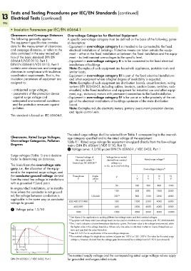
1 Voltage curve: 1.2/50 µs per DIN EN 60060-1 / VDE 0432, Part 1
Surge voltages (Table 1) are a decisive
factor in determining air distances. Nominal voltage of Voltage line to neutral Rated surge voltage 2)
the supply system
derived from nominal
1)
voltage a.c.
The basis forms the overvoltage cate- (mains) per IEC 60038 3) or d.c. up to and including
gory, i.e., the allocation of the equip- Overvoltage category 4)
ment to the expected surge voltage, and
the conductor-ground voltage derived Three-phase Single- V I II III IV
from the rated line voltage in installations V phase V V V V
with a grounded Y (star) point. V
50 330 500 800 1500
In ungrounded installations, or in installa-
tions where the conductor is not ground- 100 500 800 1500 2500
ed, the voltage between conductors is 120-240 150 5) 800 1500 2500 4000
applicable in the same way as conductor
voltage to ground. 230/400 277/480 300 1500 2500 4000 6000
400/690 600 2500 4000 6000 8000
1 Voltage pulse 1.2/50
1000 1000 4000 6000 8000 12000
1) See Annex B for application to existing different low-voltage mains and their nominal voltages.
2) Equipment with these rated overvoltage levels can be used in installations in accordance with IEC 60364-4-443.
3) The / mark indicates a 4-wire three-phase distribution system. The lower value is the voltage line-to-neutral, while
% u the higher value is the voltage line-to-line. Where only one value is indicated, it refers to 3-wire, three-phase sys-
100
90 tems and specified the value line-to-line.
4) See 4.3.3.2.2 for an explanation of the overvoltage categories.
50 û 5) The nominal voltages for single-phase systems in Japan are 100 V or 100 - 200 V. The value for the rated surge
30 voltage is, however, derived from the voltage gaps line-to-neutral for a voltage level of 150 V (see Annex B)
0
(_T _)
T 1 = 1,2 µs
<__________ T 2 = 50 µs __________>
The nominal supply voltage and the corresponding rated surge voltage values apply
DIN EN 60060-1 / VDE 0432, Part 1 for grounded and ungrounded circuits.