
Page 593 - Wago_PCB_TerminalBlocksConnectors_Volume2_2015_US
P. 593
13
591
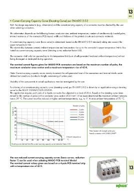
• Current-Carrying Capacity Curve (Derating Curve) per EN 60512-5-2
Both the design requirements (e.g., dimensions) and the current-carrying capacity of a connector must be checked by the user
when selecting connectors.
This information depends on the following factors: conductor size, ambient temperature, number of simultaneously loaded poles,
internal resistance of the connector, PCB layout, width and thickness of the printed circuits and connector materials.
A current-carrying capacity curve (basic curve) is determined based on the EN 60512-5-2 standard, taking into account the
upper temperature limit.
The relationship between current, ambient temperature and temperature rise up to the connector’s upper temperature limit is illus-
trated via current-carrying capacity curve (derating curve, reduction factor 0.8).
The connector shall only be operated up to this temperature limit (sum of self-generated heat and ambient temperature) without
being damaged or destroyed during operation.
The nominal current figures given for WAGO PCB connectors are based on the maximum number of poles, the
maximum conductor cross section and a maximum temperature rise of 45 K.
Note: Current-carrying capacity curves merely document the self-generated heat of the connectors and terminal blocks under
defined test conditions (conductor length, commoning of solder pins).
Usability of the components in actual applications must be investigated by the user.
Functioning of a current-carrying capacity curve (derating curve) per EN 60512-5-2 is shown by an application using a derating
curve for the MULTI CONNECTION SYSTEM:
This application requires each pole of a 4-pole connector be subjected to a load of 20 A. Based on the derating curve deter-
mined for this number of poles with a conductor cross section of 2.5 mm², it has been determined the maximum ambient tempera-
ture is 39 °C. The current must be reduced at higher ambient temperatures, e.g., to 11 A at an ambient temperature of 70 °C.
Number of poles
45
Current in A 40 2 poles
4 poles
6 poles
35
30 12 poles
24 poles
25 Conductor rated current
20
15
10 Male header with straight solder pins ®
Female connector with CAGE CLAMP
5
Ambient temperature
0 10 20 30 40 50 60 70 80 85 °C
Derating curve derived from the current carrying capacity curve (reduction factor 0.8).
The non-reduced current-carrying capacity curves (basic curves, reduction
factor 1) can be used when selecting WAGO PCB terminal blocks!
The nominal current values given are based on a 4-pole PCB terminal strip
with a temperature rise of 45 K. 13