
Page 255 - Parker - Parker Pneumatic
P. 255
Catalog PDN1000-3US Actuator Products – Rodless Cylinders
Parker Pneumatic P1Z Series - guided Version
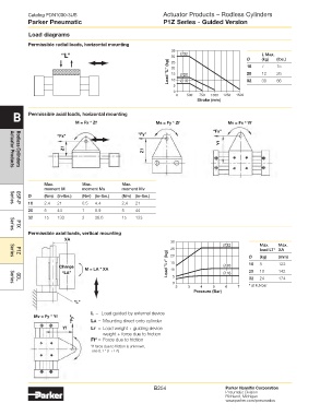
load diagrams
Permissible radial loads, horizontal mounting
35
“L” 30 ∅32 Ø L Max. (lbs.)
(kg)
Load "L" (kg) 20 ∅20 16 7 12 15
25
20
26
15
10
5 ∅16 32 30 66
0
0 500 750 1000 1250 1500
Stroke (mm)
B Permissible axial loads, horizontal mounting
M = Fx * Zf Ms = Fy * Zf Mv = Fx * yf
“Fx”
“Fx” “Fy”
yf
Zf Zf
Actuator Products
Rodless Cylinders
Max. Max. Max.
moment M moment Ms moment Mv
Ø (Nm) (in-lbs.) (Nm) (in-lbs.) (Nm) (in-lbs.)
16 2.4 21 0.5 4.4 2.4 21
Series
OSP-P
20 5 44 1 8.9 5 44
32 15 133 3 26.6 15 133
P1X
Permissible axial loads, vertical mounting
Series
Xa
30
∅32 Max. Max.
25 load LT* XA
Load "LT" (kg) 15 Ø (kg) (mm)
20
P1Z
Series
122
5
16
Charge M = la * Xa 10 ∅20
“la” 5 ∅16 20 10 142
0 32 24 174
GDL
Series
2 3 4 5 6 7 * at 6.5 bar
Pressure (Bar)
“l”
l = Load guided by external device
Mv = Fy * yf
“Fy” la = Mounting direct onto cylinder
yf lt = Load weight + guiding device
weight + force due to friction
Ff* = Force due to friction
*If force due to friction is unknown,
use 0.1 * (L + LA)
B254 Parker Hannifin Corporation
Pneumatic Division
Richland, Michigan
www.parker.com/pneumatics