
Page 221 - Wago_Rail-MountedTerminalBlockSystems_Volume1_2015_US.pdf
P. 221
" 5
219
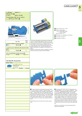
6 - 35 mm² AWG 8 - 2
400 V/6 kV/3 2
I N 125 A 600 V, 125 A2
Terminal block width 16 mm / 0.63 in
L 23 mm / 0.91 in 3
< 44,5 mm/1.75in > 1 Max. connector size: 16 mm²
2 400 V = rated voltage
8 kV = rated surge voltage
3 = pollution degree
(also see Section 14)
3 Strip length, see packaging or instructions.
< 49,5 mm/1.95 in > 4 See bottom of column 5
<_______________ 114 mm/4.49 in _______________> 5 See bottom of column 6
Pack. The new 35 mm²/AWG 2 terminal blocks are the latest 5
Item No. ®
Unit addition to WAGO TOPJOB , the professional range of
1-conductor N-disconnect terminal block rail-mounted terminal blocks for building installation. These
terminal blocks, which include an end plate, are only
blue 785-613 4 15 16 mm wide. Their compact design allows them to fit into
standard distribution box. The lower conductor entry
1-conductor power distribution disconnect terminal makes it much easier to terminate 35 mm²/AWG 2 con-
ductors.
block Furthermore, the N-busbar holder is integrated in the termi-
gray 785-623 5 15 nal block, making any separate holder redundant.
Other terminal blocks with the same profile:
Through 785-601 Page 216
Item-Specific Accessories
Busbar carrier,
not suitable as end stop,
for DIN 35 rail,
1.5 mm thick
(4x25)
blue 783-321 100 (4x25)
100
4 For the construction and operation of power installa- 5 According to DIN VDE 0100-710 “Requirements for
tions in fire hazardous locations or public buildings – such operating facilities, rooms and special installations = medi-
as conference centers, stores, hospitals, schools, theaters, cal facilities”, equipotential bonding conductors shall be
hotels. – the DIN VDE 0100-710 or DIN VDE 0100-718 run on a potential equalization busbar. The potential
standards shall be observed. DIN VDE 0100-482 shall be equalization busbar and the protective ground conductor
observed for fire hazardous locations. These VDE mandate busbar must be accommodated in a common housing and
determine that every neutral conductor must be provided be connected by means of a disconnectable connection
with a disconnection device so, e.g., insulation testing is using a copper conductor with a minimum cross section of
possible for every circuit without disconnecting the N-con- 16 mm²/AWG 6. Furthermore, all equipotential bonding
ductor. conductors must be connected to the potential equaliza-
tion busbar and clearly arranged so they can be discon-
WAGO N-disconnect terminal blocks meet this require- nected individually and accessed at any time. Depending
ment. on their function, they must be provided with captive mark-
ing.
WAGO power distribution disconnect terminal blocks
meet these requirements.